
Axial Flux Halbach Arrays for Coreless Dual-Rotor Actuators: Sizing Disc Deflection, Mitigating Multi-Kilonewton Axial Attraction, and Engineering Dynamic Air-Gap Stability
Design axial flux Halbach arrays for coreless dual-rotor actuators: size multi-kN attraction forces, disc deflection, bearing preload, and thermal air-gap margins.
Axial flux Halbach arrays concentrate magnetic flux toward the winding in coreless dual-rotor permanent magnet (AFPM) actuators. A stationary, non-magnetic stator sits between two synchronized rotor discs. Removing stator iron removes its core losses and the usual tooth-related cogging mechanism; Halbach magnetization can reduce the need for ferromagnetic back-iron. The engineering trade-off is structural: carrier plates must resist inter-rotor attraction while maintaining two running clearances. Flux density, inertia savings, and torque density depend on geometry, magnet volume, temperature, and winding design, rather than a universal improvement percentage.
The worked screening cases below produce approximately 2.5 kN and 5.8 kN of axial attraction per disc under their stated field assumptions. These are calculated examples, not a force range guaranteed for every actuator. If structural carrier discs lack sufficient flexural stiffness, attraction deflects the discs inward, reducing running clearances and risking contact with copper or printed circuit board (PCB) stator windings.
This engineering guide provides mechanical leads, electrical machine architects, and procurement managers with a first-principles framework for sizing disc deflection, selecting carrier materials, preloading duplex bearing systems, and specifying manufacturing tolerances for custom axial Halbach rotors. If you already have system-level envelope requirements, consult our axial Halbach array manufacturing path alongside the calculations below.
Published and content reviewed: November 8, 2026. Scope: global engineering procurement; dual-rotor ironless axial-flux permanent magnet machines. Numerical examples below are illustrative calculations, not measured Halbach Magnet product performance or certified design limits. This guide supports preliminary sizing and RFQ preparation; electromagnetic and structural finite element analysis (FEA), bearing-life calculations, thermal assessment, and prototype testing remain application-specific.
The design problem involves four interdependent constraints: establishing working axial flux without back-iron mass; sizing rotor carrier discs against multi-kilonewton flexural deflection; budgeting mechanical and thermal air-gap clearances; and fixturing opposing Halbach magnet segments during assembly.
1. Electromagnetic Topology: One-Sided Flux Enhancement Across an Air-Cored Gap
The Double-Rotor Internal-Stator Architecture
The dual-rotor ironless axial flux machine consists of three coaxial elements aligned along the central rotational axis ():
- Rotor Disc 1 (Upper/Front): Carries an annular Halbach array of magnetic poles mounted to a structural carrier plate rotating at angular velocity .
- Stationary Coreless Stator: Positioned in the central plane (), containing slotless copper windings (multi-strand Litz wire coils or multilayer high-copper-weight PCB traces) encapsulated in structural epoxy resin.
- Rotor Disc 2 (Lower/Rear): Carries an identical, mirrored Halbach array rotating synchronously on the common shaft, arranged in north-facing-south alignment to drive magnetic flux unidirectionally across the stator.
With no ferromagnetic stator teeth, ideal tooth-related cogging torque is zero. This does not eliminate current-induced torque ripple, magnet harmonics, bearing friction, or disturbances from nearby ferromagnetic hardware. Precision motion still requires suitable commutation, feedback, and assembly tolerances.
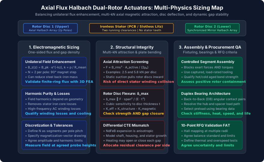
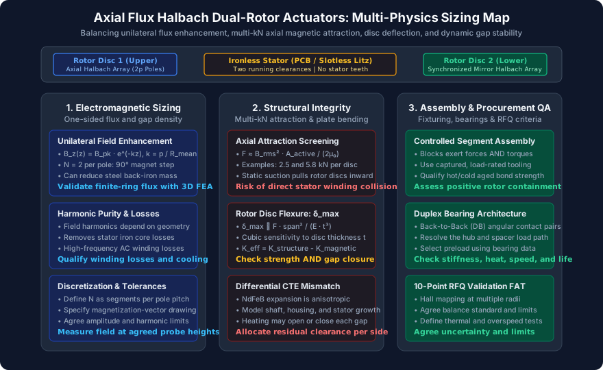
Figure 1: Systems engineering decision map for coreless axial flux Halbach actuators. Each mechanical and electromagnetic allocation requires coupled multi-physics verification.
Governing Harmonic Equations and Unilateral Field Concentration
Define as the number of equal-width magnet segments per magnetic pole pitch . The magnetization direction advances by per segment. Thus gives a step and four segments per complete pole pair; gives a step and eight segments per pole pair. The following four-direction sequence illustrates , with the order mirrored as needed to concentrate flux toward the stator:
Segment 1: Axial North (+z)
Segment 2: Circumferential / Tangential (+theta)
Segment 3: Axial South (-z)
Segment 4: Circumferential / Tangential (-theta)
The fundamental spatial wave number of the array at the mean radius is:
k = pi / tau_p = p / R_mWhere is the fundamental pole-pair count, is the outer active magnetic radius, and is the inner active magnetic radius.
On the active stator-facing surface (), the tangential and axial flux components superimpose constructively. On the exterior back surface (), the components interfere destructively. For an idealized linear Halbach distribution of magnet axial thickness , the peak fundamental axial flux density at distance from the magnet face decays exponentially:
B_z(z) = B_r * (1 - e^(-k * h_m)) * (sin(pi / (2*N)) / (pi / (2*N))) * e^(-k * z)Here denotes magnet remanence, and the expression estimates the single-array fundamental amplitude under an idealized linear, infinite-width approximation with relative permeability near unity. It is not the combined field of two finite annular rotors. Edge leakage, radial variation, segment gaps, temperature, and the opposing array require a three-dimensional field model. In the force equation below, names the radial field component to avoid confusing it with remanence.
Conventional surface-mounted permanent magnet (SPM) rotors commonly use steel back-iron sized against flux saturation and structural requirements. Halbach arrays can concentrate flux on the working side and permit a non-ferromagnetic carrier, such as titanium or a qualified composite. Finite segmented rings still leak flux; neither a back-face field limit nor an inertia reduction follows from topology alone. Compare complete rotor assemblies, including hubs, adhesive, retention bands, and any extra carrier thickness needed for stiffness.
For relevant modeling approaches, see Vatani and colleagues' analytical and FE modeling study. For a related comparison topic, see Chulaee and colleagues' torque and power capability study. These references concern specific machine designs; their titles and bibliographic records do not establish a universal percentage gain for a new actuator.
2. Multi-Kilonewton Axial Magnetic Attraction: Sizing the Collapse Load
Derivation via the Maxwell Stress Tensor
While eliminating the stator iron removes normal iron-to-magnet attraction, the two opposing rotor discs now face each other directly across the composite non-magnetic gap . Because the magnetic poles are arranged in an attracting configuration (North on Disc 1 opposing South on Disc 2 to maximize axial working field ), a powerful static magnetic attractive force pulls the two spinning rotor discs toward each other.
The normal axial force acting on each rotor disc is calculated by integrating the Maxwell stress tensor over the active annular pole surface:
sigma_z = (B_z^2 - B_theta^2 - B_radial^2) / (2 * mu_0)At an ideal symmetric mid-plane, transverse field components can cancel. If their stress contribution is negligible and the integration plane captures the relevant flux, a screening estimate for axial attraction is:
F_axial = integral (B_z(r, theta)^2 / (2 * mu_0)) * r dr dthetaFor a sinusoidal field with approximately constant peak amplitude across the active annulus, the spatial root-mean-square field is over :
F_axial = (B_peak^2 * A_active) / (4 * mu_0)This approximation omits fringing outside the active annulus and transverse stress. Use the full Maxwell stress tensor over an appropriate surface for final force extraction. Specify whether a supplied field value is peak or RMS: confusing them changes this estimate by a factor of two.
Numerical Sizing Example: High-Torque Robotics Joint
Consider a representative direct-drive robotic actuator sized for an anthropomorphic humanoid shoulder or quadruped hip joint:
- Outer magnet radius: ()
- Inner magnet radius: ()
- Active magnetic annular area:
A_active = pi * (0.085^2 - 0.055^2) = pi * (0.007225 - 0.003025) = 0.013195 m^2 (131.95 cm^2) - Peak fundamental air-gap axial flux density:
- Permeability of free space:
Substituting into the force equation:
F_axial = (0.98^2 * 0.013195) / (4 * 1.2566 * 10^-6)
F_axial = (0.9604 * 0.013195) / (5.0265 * 10^-6)
F_axial = 0.012672 / (5.0265 * 10^-6) = 2,521 N (~257 kgf) per disc
For larger aerospace actuators ():
F_axial = (1.1025 * 0.0264) / (5.0265 * 10^-6) = 5,790 N (~590 kgf) per discThe larger illustrative case produces approximately 5.8 kN per disc. Equal and opposite forces do not remove local plate bending. Carrier plates, hubs, spacers, and joints must close the load path; bearing reactions depend on how those parts are supported. Evaluate the two rotor-to-stator clearances separately rather than treating their sum as clearance available to either disc.
3. Rotor Disc Bending Deflection and Mechanical Air-Gap Budget
Circular Plate Flexure Mechanics
The rotor carrier disc behaves mechanically as a circular annular plate clamped at the inner shaft hub () and subjected to a distributed axial magnetic load over the magnet track (). Under pure bending, the maximum out-of-plane deflection occurring at the outer perimeter is governed by the plate flexural rigidity :
D = (E * t_disc^3) / (12 * (1 - nu^2))
delta_max = C_bc * (F_axial * (R_o - R_{hub})^2) / D
Where:
- is the Young’s modulus of the carrier disc material.
- is the axial thickness of the structural carrier plate.
- is Poisson's ratio.
- is a dimensionless coefficient dependent on hub ratio, load distribution, annulus geometry, and support conditions; obtain it from an applicable plate solution or a documented structural model.
The isotropic thin-plate approximation excludes ribs, joint slip, large deflection, and composite laminate anisotropy. For CFRP, use laminate bending stiffness rather than substituting a tensile modulus into the isotropic equation. Include hub and shaft compliance when extracting the displacement that actually closes the gap.
Notice the critical cubic relationship: disc stiffness scales with and linearly with . Increasing carrier thickness from to reduces bending deflection by a factor of:
(4.5 / 3.0)^3 = 1.5^3 = 3.375 (a 70.4% deflection reduction)However, adding plate thickness directly increases the actuator's axial length and rotational inertia (), penalizing step response and acceleration bandwidth.
For preliminary thickness sizing, hold material, load, and boundary conditions fixed: . If an assumed reference model gives 0.30 mm deflection for a 3.0 mm carrier and the allocated limit is 0.08 mm, the scaling gives . This is a reproducible sensitivity example, not a validated carrier design. Recompute magnetic attraction at the deflected gap before accepting the thickness.
Dynamic Air-Gap Stack-Up Allocation
To prevent catastrophic rotor-stator contact during high-speed operation, the nominal single-sided clearance between the magnet surface and the stator surface must absorb six distinct error contributions:
c_nom >= delta_flex + delta_TIR + delta_bearing + delta_thermal + delta_tol + c_safetyIllustrative one-sided allocations, not standard limits:
1. delta_flex: Elastic plate bending under the specified magnetic load (0.10 mm)
2. delta_TIR: Maximum one-sided approach from assembled axial runout (0.03 mm)
3. delta_bearing: Support translation and tilt at the active radius (0.02 mm)
4. delta_thermal: Worst closing differential thermal displacement (0.05 mm)
5. delta_tol: Unabsorbed magnet, stator, and bond-line tolerances (0.05 mm)
6. c_safety: Residual clearance after modeled loads and errors (0.25 mm)These example allocations total 0.50 mm. With single-sided nominal clearance , the additional unallocated margin is 0.15 mm. Increasing plate bending to 0.30 mm raises the requirement to 0.70 mm and fails this budget. Check both sides, hot and cold, during shock and at operating speed. Define the runout measurement datum and avoid counting the same assembly error twice; TIR is peak-to-peak and is not automatically the one-sided closing displacement.
4. Rotor Carrier Material Selection and Procurement Trade-offs
Selecting the carrier disc material requires balancing bending stiffness and inertia, electrical conductivity and rotor heating, thermal expansion mismatch, and manufacturing tolerance. A high tensile specific modulus alone does not establish plate stiffness at fixed mass: thickness, laminate construction, hub geometry, and ribs also matter. Conductive carriers can develop eddy-current losses from time-varying fields, even when the fundamental field is nearly stationary in the rotor frame.
The following six-row matrix is a qualitative procurement screen, not a material certificate or a price quotation. Obtain grade-specific properties at operating temperature and compare actual machined or molded assemblies.
| Material | When to investigate it | Main design boundary | Evidence to request with the RFQ |
|---|---|---|---|
| Aluminum 7075-T6 | Machined prototype carriers with room for adequate section thickness | Conductivity, thermal expansion, and hub compliance may govern before yield strength | Temper certificate, hot/cold flatness results, modeled bending and rotor losses |
| Titanium Ti-6Al-4V (Grade 5) | Metal carriers where conductivity, temperature, and packaging merit the machining cost | Lower conductivity does not eliminate eddy heating or thermal mismatch | Material certificate, finished-part inspection, thermal and loss assessment |
| Quasi-isotropic CFRP | Inertia-sensitive designs with a qualified laminate and hub joint | Carbon fibers conduct electricity; bending stiffness and expansion depend on layup | Laminate schedule, bending stiffness matrix, electrical properties, hub and bond qualification |
| Austenitic stainless steel 316L | Corrosion-driven designs where additional rotating mass is acceptable | Density, thermal growth, and processing-dependent magnetic response | Material and permeability checks, mass/inertia calculation, corrosion requirements |
| Inconel 718 | Temperature or strength requirements that justify a nickel-alloy carrier | High strength does not by itself reduce elastic deflection; dense parts penalize inertia | Heat-treatment record, fatigue basis, stiffness analysis, machining quotation |
| PEEK-CF30 | Polymer-composite concepts after stiffness and creep screening | Fiber orientation, temperature, moisture, and creep affect performance; conductivity is grade-dependent | Supplier datasheet, directional properties, creep curves, environmental and joint tests |
Engineering Selection Rule
Compare aluminum, titanium, and a qualified composite using the same force map and maximum permitted gap closure. Reject a candidate that meets strength but exceeds the deflection or thermal budget. For composite carriers, specify the laminate and hub interface together; for metals, include the finished geometry and eddy-loss assessment. Ask suppliers to quote equivalent acceptance requirements rather than comparing raw material prices.
5. Bearing Architectures, Preload Sizing, and Overhung Moment Management
Bearing Arrangement Mechanics
For two attracting rotor assemblies, mutual magnetic forces are equal and opposite. In the ideal coreless arrangement, translating a non-magnetic stator between rotors at fixed separation does not create two independent iron-to-magnet attraction loads. The magnetic interaction between the rotors remains an internal force:
F_rotor_1 + F_rotor_2 = 0 (mutual rotor interaction only)The load path still matters. With both discs fixed to a common shaft and spacer, much of the clamp load may close through hubs, joints, and the spacer. With independently supported discs, bearings and housings may carry substantial reactions. Draw free-body diagrams before assigning the per-disc magnetic force as bearing thrust or preload. Include external actuator loads, gravity, acceleration, joint compliance, and nearby magnetic steel separately.
K_magnetic = -dF_attraction / dg
K_effective = K_structure - K_magnetic
Here is the total magnet-face separation and both stiffnesses use the same closing-displacement coordinate. Since attraction generally rises as separation falls, it reduces effective restoring stiffness. A necessary local static stability condition is . For example, an assumed structural gap stiffness of 2,000 N/mm and a modeled attraction gradient of 800 N/mm leave 1,200 N/mm effective stiffness. These inputs are illustrative, not typical values for all Halbach rotors.
g_operating = g_unloaded - closure_1 - closure_2Iterate the field and structural models at the loaded gap. Check tilt modes as well as parallel closure: one edge may contact while the average gap remains acceptable. Positive static stiffness is insufficient for dynamic approval; calculate coupled modes with magnetic stiffness and compare them with rotational orders, electrical force harmonics, and the duty-cycle excitation spectrum. Correlate the predicted hot running gap with instrumented prototype measurements.
Duplex Angular Contact Pairs vs. Crossed Roller Bearings
Bearing selection follows calculated reactions, speed, stiffness, service life, and available envelope. Deep-groove bearings are not automatically excluded, but their axial and moment compliance must fit the gap budget. Two alternatives worth comparing are:
-
Back-to-Back (DB) Duplex Angular Contact Bearings:
- Separated effective load centers can provide useful moment stiffness.
- Select contact angle, spacing, fits, and preload from the bearing manufacturer's load-deflection and life data.
- Check hot preload, minimum load, lubrication, and heat generation. Do not set preload equal to rotor attraction without resolving the support load path.
-
Crossed Roller Bearings (CRB):
- Alternating cylindrical rollers oriented at in a single compact bearing envelope.
- A compact arrangement can support radial, axial, and moment loading.
- Evaluate the selected bearing's speed rating, friction, preload class, and housing requirements; no universal stiffness multiplier applies relative to an angular-contact pair.
For a directly relevant mechanical-design reference, see Geng, Zhang, and Wang's Halbach rotor study. When preparing a supplier review, bring the force map, support drawing, and clearance allocation to the axial Halbach manufacturing discussion.
6. Circumferential Halbach Assembly Mechanics: Fixturing and Adhesive Sizing
Segment Forces and Assembly Control
While opposing rotor discs attract axially, individual segments also experience forces and torques during insertion. Adjacent blocks may attract, repel, or rotate depending on magnetization, position, and the surrounding assembly. A right-angle difference in magnetization does not imply universal repulsion at every interface.
For the example, neighboring magnetization directions differ by . Derive insertion loads and torques from the actual partially assembled geometry, not remanence alone. Size fixture reactions against the worst assembly step as well as the completed rotor configuration.
Unconstrained segments can move abruptly, pinch tooling, or chip brittle NdFeB edges. Plan captured insertion and controlled separation of the two rotor discs, including maintenance and disassembly.
Non-Magnetic Tooling and Stepwise Insertion
A supplier assembly plan should document tooling materials, reaction loads, insertion sequence, and inspection hold points:
- Fixturing Materials: Use low-magnetic-response tooling where attraction could compromise control. Verify permeability of finished stainless tooling, and qualify wear surfaces, stops, and load capacity. Select materials for the actual fixture rather than assuming one alloy suits all operations.
- Stepwise Insertion Sequence:
- Example Phase 1: Position and capture axial segments in carrier pockets.
- Example Phase 2: Insert intermediate tangential segments with guided tooling and positive stops. Validate this sequence for the actual pole pattern; it is not mandatory for every array.
- Positive Mechanical Retention Features:
Evaluate pockets, covers, bands, or other containment against centrifugal, magnetic, thermal, and fault loads. For a rotating segment of mass at centroid radius , the basic centrifugal load is:
F_centrifugal = m * omega^2 * r_c
Structural Adhesive Selection and Thermal Degradation
The adhesive bond line transfers magnetic, centrifugal, and thermal mismatch loads. Hot shear strength, peel resistance, creep, moisture aging, magnet coating adhesion, and cure quality all matter. A room-temperature strength value or glass-transition temperature alone cannot qualify the joint. Test representative coated magnet-to-carrier coupons and assess the retained assembly under the specified duty cycle.
Procurement specifications should define:
- Bond-line and surface preparation: Adhesive grade, coating compatibility, thickness control, surface cleanliness, and traceability.
- Temperature and load qualification: Allowable joint stresses derived from hot/cold aged tests with the required design factors; specify continuous, transient, and storage temperatures separately.
- Validated processing: Mixing, any supplier-approved degassing, cure schedule, witness coupons, and acceptance checks for voids or incomplete cure. Vacuum level and filler choice follow the selected adhesive process.
For rotor retention sleeve guidelines across extreme operational envelopes, review our companion analysis on rotor retention sleeve materials.
7. Sourcing and Engineering RFQ Validation Checklist
Use this 10-point checklist when drafting an RFQ for custom axial Halbach rotors to ensure all multi-physics boundary conditions are accounted for before tooling fabrication:
- 1. Active Envelope & Magnet Geometry: Specify inner radius , outer radius , magnet axial thickness , pole-pair count , and segments per pole pitch. Include the magnetization-vector drawing and mirrored rotor orientation.
- 2. Static Attraction Load Rating: Supply the force map versus separation at temperature and tolerance extremes. Agree strength and fatigue factors for the actual materials and load cases; do not substitute a yield factor for gap stability.
- 3. Out-of-Plane Deflection Limit: Allocate maximum closure per disc from the complete clearance budget. Specify support boundaries, coupled magnetic stiffness, speed, and load conditions for verification.
- 4. Total Indicated Runout (TIR): Define datum, measurement radius, temperature, assembly state, and the one-sided displacement used in the gap budget. Agree the numeric limit with the supplier.
- 5. Dynamic Balancing: Specify the applicable current balancing standard and edition, rigid or flexible rotor behavior, maximum service speed, correction planes, and residual unbalance per plane. Agree the grade from the application rather than assuming G2.5 is universally sufficient.
- 6. Magnet Grade & Coercivity Margin: Request supplier-specific temperature-dependent demagnetization curves and evaluate worst-case armature reaction and fault currents. SH, UH, or EH suffixes do not guarantee immunity to irreversible demagnetization.
- 7. Carrier Material & CTE Match: Explicitly declare carrier material (e.g., Ti-6Al-4V or Quasi-Isotropic CFRP) and verify differential thermal expansion will not buckle magnet joints or exceed adhesive shear limits.
- 8. Mechanical Retention Strategy: Define maximum service and qualification overspeeds, duration, temperature, and containment criteria. Centrifugal load scales with speed squared: an illustrative 1.5-times speed condition produces 2.25-times centrifugal load, before other factors.
- 9. Adhesive Qualification & Cure Schedule: Require representative joint test data, hot/cold aged allowables, documented cure records, and an inspection plan compatible with the magnet coating and carrier.
- 10. 3D Hall Probe Field Acceptance Mapping: Define probe height, temperature, angular and radial sampling, calibration uncertainty, and agreed limits for fundamental amplitude, harmonic distortion, and pole-to-pole variation. Confirm whether inspection covers isolated rotors or the assembled pair.
8. Frequently Asked Questions
Q1: Why not build a single-rotor axial flux machine to avoid multi-kilonewton attraction forces?
A: A single rotor facing an ironless winding avoids attraction to a second rotor, but provides a different field distribution and may need more magnet volume or another flux-return arrangement for the required torque. A single rotor facing an iron-cored stator still attracts the stator iron. Compare complete topologies at equal envelope, thermal limit, winding loading, and magnet volume; neither a fixed flux penalty nor automatic torque doubling follows from rotor count alone.
Q2: How does thermal expansion affect the running air gap at elevated temperatures?
A: Track the signed displacement of each magnet face and each stator face relative to the same datum. Shaft and housing growth, winding-resin expansion, plate bowing, and bond-line deformation can either open or close a gap. NdFeB expansion is anisotropic: use supplier data and transform each segment's material axes into rotor coordinates. Tangentially and axially magnetized segments cannot share an assumed axial coefficient. A thermal map and measured hot runout are needed; there is no universal minimum running clearance or guaranteed thermal closure.
Q3: Can high-modulus CFRP plates completely replace titanium carriers in volume production?
A: CFRP is a candidate after laminate, hub, bond, thermal, and overspeed qualification. A balanced symmetric layup can reduce coupling, but stacking sequence still determines bending stiffness and processing distortion. Carbon fibers are electrically conductive, so a polymer matrix does not establish zero rotor eddy loss. Define final flatness and surface finishing without cutting critical reinforcement. A metal hub insert or another qualified torque-transfer interface may be needed; compare measured finished-assembly inertia and repeatability before approving substitution.
Q4: What happens if one rotor disc is angularly misaligned relative to the other on the common shaft?
A: For equal sinusoidal field contributions at the mid-plane, a relative electrical phase offset reduces their combined fundamental amplitude by relative to perfect alignment, with . Finite geometry and harmonics require a full field solution. A fixed phase error may also change inter-rotor torque and force distribution; force ripple and tilt are not inevitable in every symmetric geometry. Set indexing tolerance from the permitted field, torque, and stress errors rather than applying a universal electrical-angle limit.
Q5: Why is high coercivity (e.g., N42SH or N38UH) essential even if the stator has no iron teeth?
A: Ironless windings can still generate an opposing armature field during normal peak current or a fault. Demagnetization margin depends on local magnet temperature, geometry, permeance, material curves, and current waveform. Use the magnet supplier's temperature-dependent curves in the operating-point analysis, including partially assembled conditions where relevant. A catalog maximum temperature or grade suffix alone does not approve the design; N42SH, for example, must not automatically be treated as meeting every UH coercivity requirement.
Q6: What instrumentation is required to verify Halbach array field uniformity before motor assembly?
A: Use a calibrated Hall probe with a repeatable axial and rotary positioning system. Record measurement height, temperature, angular sampling, and multiple radii; measure transverse components when the acceptance model requires them. Compare the measured fundamental with the same sampling geometry in FEA. Define field THD as the root-sum-square of the specified higher-harmonic amplitudes divided by the fundamental; pole-to-pole deviation is a separate metric. Neither a particular stage technology nor a universal percentage limit is mandatory. Include measurement uncertainty in the agreed acceptance decision.
9. Sourcing Halbach Magnets and Engineering Collaboration
Precision axial Halbach arrays are specialized engineered subassemblies, not commodity off-the-shelf magnet catalog items. Successful deployment requires seamless coordination between electromagnetic finite element modeling, ultra-precision CNC pocket machining, non-magnetic assembly fixturing, and dynamic balancing.
When initiating an inquiry with Halbach Magnet:
- Provide your preliminary envelope constraints (outer diameter, shaft diameter, axial stack height, and target torque).
- Clarify whether your design requires loose, factory-paired magnet segments for your own assembly line, or fully integrated, dynamically balanced rotor subassemblies with precision titanium or CFRP carrier plates.
- Review our custom engineering workflows at our axial Halbach array manufacturing resource and explore our precision manufacturing capabilities.
To review your CAD drawings, discuss mechanical retention strategies, or request a formal DFM and quotation, contact the Halbach Magnet engineering team.
Sources and References
- Geng, W., Zhang, Z., and Wang, C. (2017). Mechanical design considerations of Halbach-array rotor for a new ironless stator axial-flux PM machine. 2017 20th International Conference on Electrical Machines and Systems (ICEMS), pp. 1–6. Reference topic: mechanical design of an ironless-stator Halbach rotor.
- Vatani, M., Chulaee, Y., Eastham, J. F., and Ionel, D. M. (2024). Analytical and FE Modeling for the Design of Coreless Axial Flux Machines with Halbach Array and Surface PM Rotors. 2024 IEEE Energy Conversion Congress and Exposition (ECCE), pp. 5205–5211. Reference topic: analytical and finite element electromagnetic modeling.
- Chulaee, Y., Lewis, D., Vatani, M., Eastham, J. F., and Ionel, D. M. (2023). Torque and Power Capabilities of Coreless Axial Flux Machines with Surface PMs and Halbach Array Rotors. 2023 IEEE International Electric Machines & Drives Conference (IEMDC), pp. 1–6. Reference topic: topology-dependent torque and power comparison.
Source records checked November 8, 2026 against DOI bibliographic metadata. These are research references, not certifications of this article's examples, material selections, or supplier capabilities. No universal numerical performance gain is attributed to an uninspected full text.
Author

Categories
More Posts
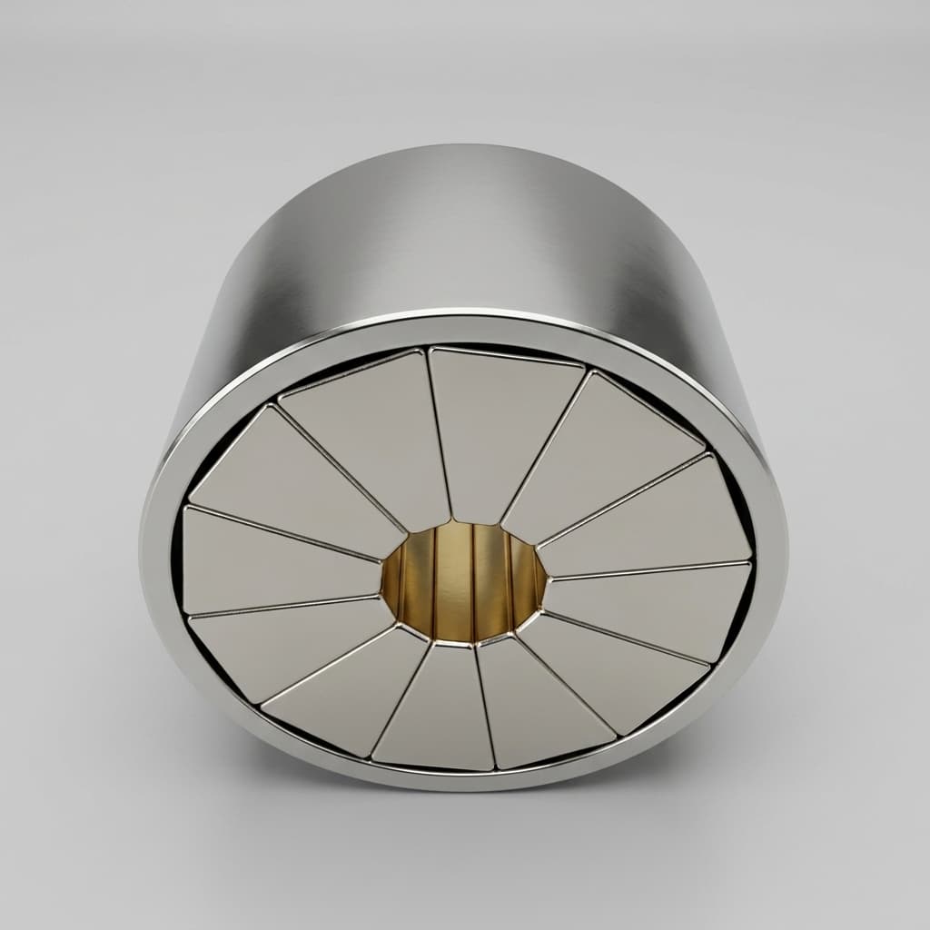
Low-HRE NdFeB vs. SmCo in Halbach Magnet Assemblies: 2026 Sourcing Guide
Compare Low-HRE NdFeB vs SmCo for global Halbach magnet assemblies in 2026. Review temperature limits, supply risks, and RFQ checks before custom sourcing.

Halbach Array Supply Chain Traceability: Preparing for EU CRMA & CEN/TS 18263:2026
Prepare Halbach magnet sourcing for EU CRMA and CEN/TS 18263:2026 with supplier data fields, recycling risks, RFQ checklist, and contact review steps.
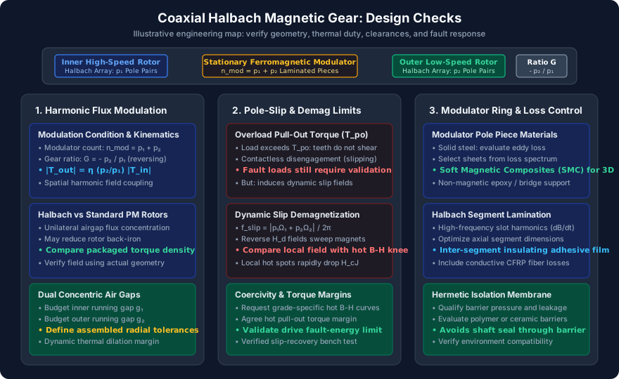
Coaxial Halbach Magnetic Gears: Sizing Modulated Flux Pole Pieces, Preventing Slip Demagnetization, and Mitigating Rotor Eddy Losses
Size coaxial Halbach magnetic gears: compare pole-piece geometry, slip protection, rotor eddy losses, and supplier evidence. Use the checklist for your next RFQ.