
Halbach Array Rotor Retention Sleeves: Carbon Fiber vs. Titanium vs. Inconel
Compare Halbach rotor retention sleeves for high-speed motors: CFRP, titanium, and Inconel trade-offs for eddy losses, thermal limits, and RFQs.
Halbach Array Rotor Retention Sleeves: Carbon Fiber vs. Titanium vs. Inconel
In high-speed electric motors, kinetic energy storage flywheels, and advanced aerospace propulsion systems, the Halbach array has become a common topology for permanent magnet (PM) rotors that need high air-gap flux density with limited rotor mass. By configuring the magnets to concentrate magnetic flux on the air-gap side while reducing it on the inner bore, engineers can reduce or remove heavy iron back-yokes in suitable designs. That can lower rotor inertia and support higher operating speeds and power density than conventional surface-PM layouts.
However, this architecture introduces a severe, highly specific mechanical challenge. Adjacent Halbach magnets produce strong repulsive forces because their magnetization vectors are rotated relative to each other. When those static forces combine with the centrifugal load generated at operating speeds often exceeding 50,000 RPM, and in some micro-turbines over 150,000 RPM, Neodymium (NdFeB) or Samarium Cobalt (SmCo) magnets can move, crack, or detach from the rotor hub if not properly contained.
To reduce rotor-burst risk, high-speed Halbach rotors require a retention sleeve (also known as a banding or retaining ring). This outer sleeve must provide high radial compression through an interference fit while surviving the thermal and high-frequency magnetic environment of the motor's air gap.
For procurement teams, supply chain managers, and mechanical motor engineers, selecting the right sleeve material is one of the most critical design decisions in the entire project. The industry generally relies on three primary material families: Carbon Fiber Reinforced Polymer (CFRP), Titanium Alloys, and Inconel. A poor match can force power derating through thermal bottlenecks, create unacceptable eddy current losses, or leave too little mechanical margin for overspeed testing.
Update Note: This guide reflects current engineering consensus and supply chain realities as of July 2026. It is a structured decision-making framework designed for hardware procurement teams and mechanical engineers specifying custom magnetic assemblies.
Scope and limits: Use this article for early material selection, supplier questioning, and RFQ preparation. It is not a substitute for rotor stress analysis, burst-speed validation, thermal FEA, or electromagnetic loss modeling using your actual rotor OD/ID, pole count, magnet grade, duty cycle, cooling method, and safety factors. For drawing-level feedback, contact the engineering team with those inputs before locking the sleeve material.
1. The Engineering Challenge: Navigating Conflicting Constraints
Designing a retention sleeve for a segmented Halbach array is an exercise in balancing coupled physics. You usually cannot optimize one variable without moving another. The three primary constraints are:
The Magnetic Air Gap Penalty
The retention sleeve sits physically between the rotor's permanent magnets and the stator's copper windings. In magnetic circuit design, the sleeve increases the effective air gap. Magnetic flux density falls as that distance increases, so the sleeve must be as thin as the stress margin allows. A material with low tensile strength requires a thicker sleeve to hold the magnets, which increases the effective magnetic air gap and reduces motor torque. This forces engineers to seek materials with the highest practical specific strength (strength-to-weight ratio).
Eddy Current Losses vs. Electrical Conductivity
In a high-speed permanent magnet machine, the stator fields fluctuate at high electrical frequencies. Any electrically conductive material passing through these changing magnetic fields will generate eddy currents. These parasitic currents swirl within the material, doing no useful work and converting magnetic energy directly into waste heat. Metallic sleeves such as titanium and nickel alloys are conductive and can suffer from these losses, whereas composite sleeves like CFRP are far less conductive through the sleeve thickness. If magnet segmentation is still under review, compare this trade-off with our guide to segmented Halbach array eddy current losses.
Thermal Management and Heat Dissipation
Heat is the enemy of all permanent magnets, particularly Neodymium (NdFeB), which loses magnetic strength and can suffer irreversible thermal demagnetization at elevated temperatures. Heat generated in the stator must not be allowed to bake the magnets, and heat generated within the magnets themselves from internal eddy currents must have a path to escape. Composites act as thermal insulators, trapping heat inside the rotor, whereas metallic sleeves conduct heat outward more effectively. For magnet-grade selection, use this together with our high-temperature demagnetization checklist for Halbach rotors.
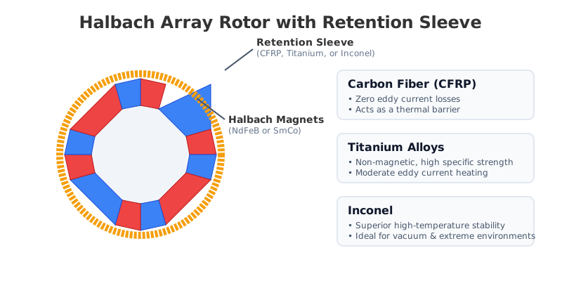
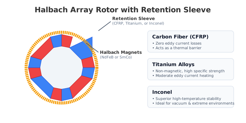 Figure 1: Cross-sectional diagram of a segmented Halbach array rotor highlighting the critical position of the retention sleeve and the outward centrifugal forces it must counteract.
2. Material Trade-Offs: Deep Dive into the Big Three
Understanding the fundamental material science of these three options is critical before sending an RFQ to a contract manufacturer.
Carbon Fiber Reinforced Polymer (CFRP)
Carbon fiber has emerged as the default choice for modern ultra-high-speed rotors, particularly in the EV and aerospace sectors. It boasts an exceptional specific strength and is electrically insulating.
- The Primary Advantage: Because CFRP is much less conductive through the sleeve than metals, it generates negligible eddy current losses in the sleeve itself for many motor designs. It is often treated as "magnetically transparent." This allows the motor to operate at high electrical frequencies without meaningful sleeve self-heating. Furthermore, its tensile strength allows for a very thin sleeve, minimizing the air gap penalty.
- Fabrication Methods: CFRP sleeves are typically applied in one of three ways:
- Press-fitting a precision-machined, pre-cured composite tube over the rotor.
- Wet filament winding, where resin-soaked carbon tow is wound directly onto the assembled magnets under high tension.
- Winding pre-preg carbon tow and curing the entire assembly in an autoclave.
- The Boundary Condition (When it fails): CFRP is a significant thermal barrier. In a Halbach rotor, heat generated in the magnets cannot easily pass outward through the carbon fiber. Furthermore, the epoxy resin matrix binding the carbon fibers together is the weak link. Standard resins can degrade above roughly 150°C, and even advanced aerospace-grade cyanate ester or bismaleimide (BMI) systems need validation near 200°C. If the rotor runs hot, the resin can soften, the carbon fibers can lose load-sharing integrity, and the sleeve may no longer maintain preload.
Titanium Alloys (e.g., Ti-6Al-4V)
Titanium is a non-magnetic metal with an excellent strength-to-weight ratio. It bridges the gap between composites and heavy superalloys, and is frequently used in environments where composites are strictly disqualified due to temperature or outgassing concerns.
- The Primary Advantage: Titanium can handle significantly higher operating temperatures than most CFRP resin systems. It also avoids polymer-resin outgassing concerns, making it attractive for kinetic energy flywheels and space applications after cleaning and process validation. It is mechanically robust, highly corrosion-resistant, and provides better thermal conductivity than composites, allowing the magnets to shed heat more effectively.
- The Boundary Condition (When it fails): Titanium is electrically conductive. In the rapidly fluctuating magnetic fields of a high-speed motor, substantial eddy currents can be induced in the titanium sleeve. This can reduce overall motor efficiency and generate heat directly adjacent to the NdFeB magnets. To mitigate this, engineers may need to increase the air gap, segment other conductive parts, or change the stator slot/pole strategy, which can reduce torque. Titanium's thermal expansion behavior also requires careful interference-fit calculation so the sleeve does not over-compress brittle magnets during assembly or thermal transients.
Inconel (e.g., Inconel 718)
Inconel is a nickel-chromium-based superalloy family. It is the heavy-duty fallback for high-temperature, corrosive, or mechanically aggressive environments where lighter materials do not provide enough margin.
- The Primary Advantage: Inconel 718 and related grades retain useful tensile and yield strength at temperatures where polymer composites are outside their normal design window. For high-temperature industrial pumps, downhole oil drilling motors, aerospace turbine generators, or high-radiation environments, Inconel can provide a large thermal and mechanical safety margin if the grade, heat treatment, and magnetic permeability are specified correctly.
- The Boundary Condition (When it fails): It is extremely heavy (dense), which significantly increases the rotor's rotational inertia—often defeating one of the main purposes of using a Halbach array in the first place. More importantly, like Titanium, it generates exceptionally high eddy current losses. Because Inconel is partially magnetic (its magnetic permeability varies depending on the specific alloy grade and the heat treatment applied), it must be carefully specified. If the wrong grade is used, the Inconel sleeve will act as a magnetic short-circuit, absorbing the Halbach flux instead of letting it pass into the air gap. Finally, machining Inconel is notoriously slow, difficult, and expensive, driving up the cost of the rotor assembly.
3. Structured Comparison for Procurement & Engineering Teams
Use this comprehensive table to evaluate which material aligns with your motor's operational envelope, thermal limits, and budget constraints.
| Decision Metric | Carbon Fiber (CFRP) | Titanium (Ti-6Al-4V) | Inconel (718) |
|---|---|---|---|
| Max Operating Temp | ~120°C - 200°C (resin limited) | ~300°C - 400°C+ (design-dependent) | ~500°C - 650°C+ (grade-dependent) |
| Eddy Current Losses | Negligible in most sleeve designs | High (requires cooling/loss design) | Very high (major efficiency hit) |
| Thermal Conductivity | Poor (Acts as an insulator) | Moderate | Moderate to Good |
| Specific Strength | Outstanding (Thinnest sleeve) | Very Good (Thin sleeve) | Moderate (Thicker sleeve required) |
| Rotor Inertia Impact | Minimal (Very lightweight) | Moderate | High (Very dense material) |
| Assembly Method | Filament winding or press-fit | Heat-shrink (Interference fit) | Heat-shrink (Interference fit) |
| Vacuum Compatibility | Requires low-outgassing resin validation | Strong after cleaning/process validation | Strong after cleaning/process validation |
| Best-Fit Use Case | Highest-speed efficiency-focused motors | Hot/vacuum rotors needing lower mass than superalloys | Extreme temperature, corrosive, or high-safety-margin rotors |
| Relative Cost (Volume) | High (Labor/Process intensive) | Very High (Material + Machining) | Highest (Material + Machining) |
4. Engineering & Sourcing Validation Checklist
When requesting quotes (RFQs) for custom Halbach rotor assemblies, you cannot afford to let your suppliers treat the retention sleeve as an afterthought. It is a highly engineered component. Use this checklist to validate the engineering competence of your magnetic assembly partner:
- 1. Multiphysics Eddy Current Simulation: Has the supplier run a detailed FEA (Finite Element Analysis) simulation to calculate the exact eddy current heating in the proposed metallic sleeve based on your stator's slot harmonics?
- 2. Interference Fit & CTE Calculation: For Titanium or Inconel sleeves, has the supplier calculated the exact temperature differential required to thermally expand the sleeve for installation? Furthermore, have they proven that the shrinkage upon cool-down will not exceed the compressive yield strength of the brittle NdFeB magnets?
- 3. Thermal Demagnetization Margin: If using CFRP, does their thermal model account for the insulating effect of the carbon fiber? Are the underlying magnets specified with a high enough intrinsic coercivity (e.g., UH, EH, or AH grade) to survive the trapped heat without permanent field loss?
- 4. Vacuum Outgassing Requirements: If the rotor operates in a vacuum, space-rated, or hermetically sealed medical environment, have all CFRP resins and bonding adhesives been vetted for Total Mass Loss (TML) and Collected Volatile Condensable Materials (CVCM) limits?
- 5. Dynamic Balancing Protocol: Is high-speed dynamic balancing performed after the sleeve is installed? This is absolutely crucial, as the sleeve application process (especially wet filament winding) can slightly shift the rotor's center of mass, leading to catastrophic vibrations at high RPMs.
- 6. Magnet Pre-Loading: Do they have specialized non-magnetic fixturing capable of assembling the violently repelling Halbach segments precisely before the sleeve is applied?
5. Frequently Asked Questions (FAQ)
Q: Can we use a stainless steel sleeve to save money on prototyping?
A: Standard austenitic stainless steels (like 304 or 316) are generally non-magnetic in their annealed state. However, they can become slightly magnetic when cold-worked or machined during the manufacturing process. This induced magnetism can interfere with the precise flux concentration of the Halbach array. Additionally, their electrical conductivity is high, leading to severe eddy current losses. They are generally only acceptable for low-speed, low-cost applications, not high-speed rotors.
Q: How is a carbon fiber sleeve physically applied over a repulsive Halbach array?
A: There are three common methods in modern manufacturing. 1) Press-fitting: A pre-manufactured CFRP tube is forced over the rotor using a hydraulic press. This requires incredibly tight machining tolerances on the magnets. 2) Wet filament winding: Carbon tow is pulled through a resin bath and wound directly onto the assembled magnets under high tension. This is highly effective but messy. 3) Pre-preg winding: Pre-impregnated carbon tow is wound onto the rotor, and the entire assembly is cured in an industrial oven. Note that any method requiring oven curing must keep temperatures below the magnet's thermal threshold.
Q: Does the retention sleeve increase the magnetic air gap?
A: Yes, absolutely. Because the sleeve sits between the permanent magnets and the stator teeth, its physical thickness represents "dead space" magnetically. This is known as the effective air gap. This is why high specific-strength materials (which allow for thinner sleeves, like CFRP) are heavily prioritized by motor designers, even if they are more expensive to manufacture.
Q: What if the motor is flooded with cooling fluid?
A: If the rotor is submerged or flooded with a cooling fluid (like ATF or water-glycol in some direct-cooled EV motors), Carbon Fiber becomes problematic because the fluid can slowly degrade the epoxy resin over time. In fluid-flooded environments, Titanium is often preferred for its chemical resistance, though Inconel may be required for highly corrosive industrial fluids.
6. Review Your Next Halbach Assembly Specification
Selecting the right retention sleeve strongly affects whether a permanent magnet rotor can meet speed, thermal, and reliability targets. Whether your aerospace application needs the low-loss efficiency of Carbon Fiber, or your downhole pump requires the high-temperature survivability of Inconel, precision engineering is non-negotiable.
At Halbach Magnet, we do far more than just supply raw magnets. We support advanced engineering and procurement teams with full-assembly design reviews, thermal limit multiphysics modeling, and high-precision manufacturing for complex, sleeved segmented arrays.
Review our manufacturing capabilities to understand how we maintain sub-millimeter tolerances on sleeved rotors, or explore our Halbach cylinder options for your next high-speed project.
Contact our engineering team today to request a detailed manufacturability review, tolerance stack-up analysis, and RFQ for your high-speed rotor design.
Sources & References
- Calnetix Technologies. Rotor Retention and Loss Reduction for High-speed PM Motor Generators, technical paper on composite/metallic rotor retention and loss mechanisms.
- Wang, T., et al. (2022). Research on Stress Design and Manufacture of the Fiber-Reinforced Composite Sleeve for the Rotor of High-Speed Permanent Magnet Motor, Energies, 15(7), 2467.
- Lee, S.-H., et al. (2023). A Novel Sleeve Design to Reduce the Eddy Current Loss of High-Speed Electrical Machines, Machines, 11(7), 756.
- Cansiz, A., et al. (2022). Permanent Magnet Machines for High-Speed Applications, World Electric Vehicle Journal review covering rotor stress, sleeve design, and high-speed PM machine constraints.
Author

Categories
More Posts
Low-HRE NdFeB vs. SmCo in Halbach Magnet Assemblies: 2026 Sourcing Guide
Compare Low-HRE NdFeB vs SmCo for global Halbach magnet assemblies in 2026. Review temperature limits, supply risks, and RFQ checks before custom sourcing.
The Engineer’s Guide to Halbach Magnet Assemblies: Costs, Tolerances, and Sourcing Checklist
A comprehensive guide for engineers and procurement teams on sourcing Halbach magnet assemblies, balancing tolerances, manufacturing costs, and structural integrity.
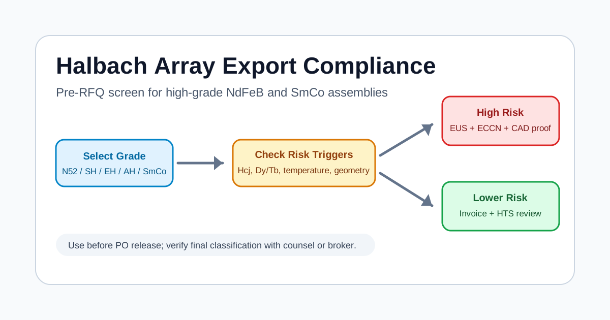
Navigating Export Controls and Dual-Use Compliance for High-Grade Halbach Arrays
Procurement guide to sourcing high-grade NdFeB and SmCo Halbach arrays without dual-use export control delays, customs seizures, or legal penalties.