
Choose a working region first
An inward bore field, outward motor field and axial face field need different models and inspection paths.
[R1]Size your rotor, cylinder or disc brief, then use the evidence below to define manufacturing and inspection requirements.
Published and reviewed by Halbach Magnet. Project capability, price and delivery require a written quotation.
Request DFM & quoteCheck geometry and tip speed, then copy a manufacturing brief. Results update instantly.
All fields are required. Defaults are an illustrative 65 / 35 × 45 mm, 15,000 RPM rotor, not a qualified product.
10–1,200 mm; magnet envelope
4–1,150 mm; smaller than OD
3–800 mm; active magnet length
0–150,000 RPM; 0 for static use
0.1–50 mm; see topology definition below
−200–500°C input range, not a material rating
Gap means radial distance from magnet OD for an outward field, inward from the bore wall for an inward field, or axial distance from the active face for a disc.
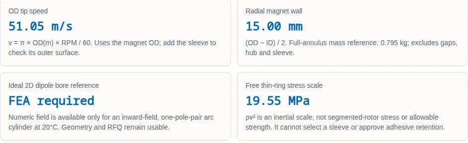
51.05 m/s
v = π × OD(m) × RPM / 60. Uses the magnet OD; add the sleeve to check its outer surface.
15.00 mm
(OD − ID) / 2. Full-annulus mass reference: 0.795 kg; excludes gaps, hub and sleeve.
FEA required
Numeric field is available only for an inward-field, one-pole-pair arc cylinder at 20°C. Geometry and RFQ remain usable.
19.55 MPa
ρv² is an inertial scale, not segmented-rotor stress or allowable strength. It cannot select a sleeve or approve adhesive retention.
Export includes assumptions and unknowns. Copying does not send an inquiry.
An inward bore field, outward motor field and axial face field need different models and inspection paths.
[R1]A dipole segmentation factor does not establish THD or homogeneity. Define the required measurement region and metric.
[R2]Electrical, thermal and mechanical properties of a sleeve interact. A nominal RPM or material name is not a validated assembly rating.
[R3]Specify field-map records, traceability and balance criteria; balancing itself does not certify burst strength.
[R4]Geometry and kinematics are deterministic calculations. Magnetic values use illustrative nominal remanence at 20°C (N42 1.30 T; N52 1.45 T; N38SH 1.24 T; N35UH 1.18 T; Sm₂Co₁₇ 1.08 T). These are tool assumptions, not certified lot data or temperature ratings. Density assumptions are respectively 7,500, 7,500, 7,550, 7,600 and 8,400 kg/m³.
| Output | Method | Boundary / next step |
|---|---|---|
| Wall and tip speed | t = (OD − ID) / 2; v = π × OD(m) × RPM / 60. | Magnet envelope only. Include coating/sleeve thickness for the final interface. |
| Mass reference | Full annulus volume × nominal magnet density. | Not a finished rotor mass; gaps, hub, sleeve and adhesive are excluded. |
| Ideal dipole bore field | B₂D = Br × ln(OD/ID) × sin(2π/N)/(2π/N). | Only inward p=1 arc cylinders at 20°C; μr=1, infinite length and no gaps/steel. No finite-length correction is claimed. [R1, R2] |
| Stress scale | σscale = ρv² / 10⁶ MPa (SI inputs). | Free thin-ring inertial scale only. Not local magnet stress, sleeve stress, joint load or allowable strength. |
| Force, THD and safe speed | Not calculated: public inputs do not establish these quantities. | Request a vector-resolved magnetic model, structural analysis and a test plan. |
The ideal dipole expression is a reference for comparisons, not an upper/lower bound on every real assembly. Finite length, permeability, gaps, temperature and demagnetization require project-specific treatment. [R1][R2]
| Topology | Field region | RFQ inputs | Use / boundary |
|---|---|---|---|
| Inward-field cylinder | Field in the bore; p=1 is a transverse dipole reference. | Bore diameter, working volume, axial length, end access and field uniformity. | NMR research, sensor calibration or beam optics; qualify each application separately. |
| Outward-field rotor | Field requested outside the magnet OD toward a stator. | Pole pairs, total effective air gap, stator geometry, speed and thermal duty. | Motor/generator RFQ; the bore dipole formula is not used for this case. |
| Axial annular disc | Field requested on an axial face of a ring. | Inner/outer radius, magnet thickness, axial gap and adjacent rotor/stator. | Axial-flux or face-coupling concept; requires a suitable 3D model. |
Specify the magnetization-vector convention on the drawing. The tool records a positive pole-pair count as an RFQ descriptor; it does not use that count to select an external-cylinder analytical solution. Real arrays can leak flux on the nominally weak side. [R1][R2]
| Option | Geometry | Cost / process tradeoff | Decision evidence to request |
|---|---|---|---|
| Curved arc wedges | Can follow cylindrical mating surfaces; actual gaps follow the drawing. | Profile machining, coating thickness and segment handling add cost. | Request a vector-orientation drawing and assembly tolerance stack. Do not infer THD from the arc shape alone. |
| Chorded blocks | Flat blocks can approximate a ring with designed gaps and a support structure. | Standard shapes may simplify prototypes; packaging and epoxy volume change. | A viable option when validated against the target field and mechanics; not automatically unsuitable for precision work. |
| Custom magnetized ring | Availability depends on material, orientation and magnetizing equipment. | Dedicated tooling may trade initial cost against assembly steps. | Ask for the actual magnetization pattern and measured field. A conventional multipole ring is not automatically a Halbach ring. |
| Segments N | Mechanical sector angle | Ideal dipole field factor | Unknown from N alone |
|---|---|---|---|
| 4 | 90.00° | 63.66% | THD, ppm homogeneity, assembly force and price |
| 8 | 45.00° | 90.03% | THD, ppm homogeneity, assembly force and price |
| 12 | 30.00° | 95.49% | THD, ppm homogeneity, assembly force and price |
| 16 | 22.50° | 97.45% | THD, ppm homogeneity, assembly force and price |
| 24 | 15.00° | 98.86% | THD, ppm homogeneity, assembly force and price |
| 32 | 11.25° | 99.36% | THD, ppm homogeneity, assembly force and price |
These factors apply to a specific ideal dipole geometry. They do not imply a guaranteed performance gain from adding segments to any motor. Ask the manufacturer to compare actual gaps, vector errors and acceptance metrics before increasing part count. [R1][R2]
For every rotating topology, request a model of the complete magnet–hub–sleeve system, including interference tolerance, thermal cycling and operating duty. For static cylinders, fixture and housing loads still need review. No universal RPM crossover or sleeve thickness is asserted here.
| Option | Potential role | Tradeoffs | Evidence before release |
|---|---|---|---|
| CFRP sleeve | Fiber layup and interference can provide hoop restraint. | Anisotropic conductivity, resin temperature limit, transverse heat flow and manufacturing defects. | Layup-specific properties, cure records, coupled thermal/stress analysis and an agreed test plan. [R3] |
| Metal sleeve (titanium, nickel alloy or steel) | Machinable retention surface and heat-conduction path. | Mass, thermal expansion, conductivity, magnetic permeability and added effective gap. | Actual alloy condition, fit tolerances, eddy-loss analysis and hot/cold contact pressure. [R3] |
| Adhesive joint and support housing | Positions segments and transfers loads in a designed assembly. | Coating adhesion, peel, fatigue, joint gap, cure and aging cannot be represented by one lap-shear value. | Representative joint tests and documented mechanical restraint. No adhesive-only approval is produced by this tool. [R6] |
CFRP is not an electrically perfect insulator, and a sleeve cannot eliminate all rotor losses. Its layup, contact conditions and excitation matter. Adhesive shear data must also match the actual joint, cure and temperature. [R3][R6]
| Metric | Define in the RFQ | Requested record | Limitation |
|---|---|---|---|
| Field amplitude | Component or magnitude; radius, axial plane, angle, temperature and probe uncertainty. | Mapped data plus drawing revision and instrument calibration. | No universal Tesla target is inferred from material grade. [R1, R2] |
| THD / torque ripple | Fundamental order, included harmonics, sampling, scan path and operating condition. | Raw waveform and agreed harmonic calculation; motor torque testing where needed. | Field THD and cogging torque are different metrics; neither is predicted here. |
| Bore homogeneity | DSV or ROI dimensions, peak-to-peak or RMS definition, mean field and temperature. | 3D map before/after any shimming, including repeatability. | No ppm promise without a defined measurement volume and test method. [R2] |
| Rotor balancing | Rigid/flexible behavior, correction planes, residual unbalance and agreed grade. | Balance report tied to the assembled rotor and fixture setup. | ISO 21940-11 covers rigid behavior; balance quality does not prove retention strength. [R4] |
| Vacuum compatibility | Formulation, mix/cure/bake conditions and required outgassing criteria. | Matching material test record and project-specific process documentation. | Do not treat an adhesive family name as NASA approval. [R5] |
A useful inquiry names the metric and how it will be measured. A low field-THD result does not alone establish low motor torque ripple, and bore homogeneity is meaningful only with the chosen region and statistic. Discuss instrument uncertainty and repeatability alongside tolerance limits.
Illustrative calculations and suggested next actions. These are not customer case histories or production test results.
Inputs: 65 mm OD, 35 mm ID, 45 mm length, 15,000 RPM; outward field.
Result: The tool returns 15 mm radial wall and 51.05 m/s magnet-OD tip speed. Field and retention remain open engineering tasks.
Next step: Add stator geometry, total air gap, temperature and overspeed requirements; request coupled analysis before ordering a sleeve.
Inputs: 65 mm OD, 35 mm bore, 45 mm length; p=1, 16 arc segments, nominal N42 at 20°C, 0 RPM.
Result: The ideal 2D reference is about 0.784 T. It is not the finite 45 mm cylinder field; its length/bore ratio is only 1.29.
Next step: Specify the working volume and homogeneity definition, then request 3D end-effect evaluation and a mapped first article.
Inputs: 80 mm OD, 40 mm ID, 10 mm thickness; four pole pairs, 32 segments and 0 RPM.
Result: The tool returns a 20 mm radial wall and an RFQ geometry brief. It intentionally leaves axial working field and assembly force unknown.
Next step: Provide the axial gap and opposing structure. Compare arc/block options using the same 3D field and fixture review.
| Risk | Why it matters | Mitigation | Alternative / fallback |
|---|---|---|---|
| Misuse: treating a nominal reference as actual field | A finite cylinder, nearby steel and temperature can change the result. | State the ROI and hot-spot temperature; commission a relevant model and validate a first article. | For a bench demonstration, label the reference explicitly and use measured values for acceptance. |
| Safety: releasing a rotor from ρv² alone | Segment contacts, sleeve fit, thermal expansion and rotor dynamics are missing. | Require a qualified retention and validation plan before operation. | Use a static evaluation assembly while rotational design is unresolved. |
| Cost: tightening every tolerance | Inspection, magnet sorting, fixturing and scrap may dominate the quote. | Run sensitivity analysis and assign tight tolerances to functional datums only. | Compare a standard-block prototype with a production arc design against the same acceptance test. |
| Mismatch: specifying magnetic resonance ppm for a motor | The metric may not represent torque or efficiency requirements. | Specify useful field component, harmonic orders and actual duty cycle. | Compare electromagnetic and mechanical acceptance separately. |
| Commercial: assuming public figures are a quotation | Quantity, supplier process, tooling and inspection scope remain unknown. | Request itemized tooling, recurring price, deliverables and confirmed dates. | Stage procurement as analysis → first article → repeat production. |
If the design is incomplete, start with the application, envelope and target field. Capability, inspection deliverables, price and lead time are unconfirmed until accepted in a quotation; no universal production or certification claim is made on this page.
Only an inward-field p=1 arc cylinder at 20°C receives the ideal 2D bore reference. External rotors, axial discs, other multipoles, chorded blocks and other temperatures need a suitable model; geometry and RFQ export still work.
No. It assumes infinite length, relative permeability of one, nominal remanence and no gaps or nearby steel. Actual field and homogeneity require finite-geometry analysis and measurement.
The ideal infinitely long p=1 cylinder has a uniform transverse bore field. Clearance locates the inspection region but does not change that ideal result. Finite cylinders are not assumed uniform.
No. Strong segment forces and stored magnetic energy remain. Fixture, housing, adhesive and handling requirements need review even for static assemblies.
No. Radius, material properties, interference, temperature, stress concentrations, rotor dynamics and duty matter. This tool calculates tip speed and a thin-ring stress scale, not a safe-speed rating or sleeve thickness.
No. Carbon fibers conduct anisotropically, and the magnets, hub and other rotor parts can also have losses. Use layup-specific electrical properties and the actual excitation spectrum.
No. The displayed dipole factor describes an ideal fundamental field reduction. THD also depends on pole count, geometry, gaps, vector errors and the measurement path; it must be analyzed or measured.
The drawing revision, temperature, coordinate system, scan path, vector components, calibration and uncertainty, together with the agreed field, harmonic or homogeneity definition. See the acceptance table.
No. Qualify traceability, material screening, assembly controls and accountability for outsourced processes. Vertical integration alone does not establish field or assembly quality.
Add a dimensioned drawing or CAD file, working-field target and volume, temperature and duty cycle, quantity, housing interfaces, environment and required acceptance documents. Paste the tool brief into the contact inquiry.
No public project-specific price or delivery commitment is established here. Ask for a written quotation separating engineering, tooling, first-article inspection and repeat production, with confirmed milestones.
Keep the example values clearly identified as provisional and ask for a drawing review. State the application, field or torque goal, space envelope and thermal duty so the manufacturer can propose a configuration.
Sources and scope reviewed on 27 October 2026. Published models support their stated assumptions; standards describe test scope. None of these references certifies this supplier, validates a quoted rotor or provides current project pricing. Procurement recommendations above are engineering judgments to confirm during DFM.
Analytical 2D cylinder fields; does not qualify a finite manufactured rotor or assembly fixture.
Cylinder segmentation, finite geometry, shimming and temperature context. Application guidance, not supplier capability evidence.
A specific rotor study of sleeve conductivity and thermal/mechanical effects. Its numerical losses cannot be transferred to another motor.
Balancing scope; the official listing also identifies Amendment 1:2022. This is not a burst-strength or safe-speed certification.
ASTM E595 material test records. Match formulation, cure and test conditions; a brand name alone does not establish qualification.
Example retaining-compound data showing substrate, gap, cure and temperature dependence. Confirm the latest regional/formulation TDS for the selected joint; not an approval of a segmented rotor.
Review owner: Halbach Magnet. Next scheduled engineering and source review: April 2027, or sooner if a cited source or model changes.
Send your drawing for DFM & quote