
Coaxial Halbach Magnetic Gears: Sizing Modulated Flux Pole Pieces, Preventing Slip Demagnetization, and Mitigating Rotor Eddy Losses
Size coaxial Halbach magnetic gears: compare pole-piece geometry, slip protection, rotor eddy losses, and supplier evidence. Use the checklist for your next RFQ.
Coaxial Halbach magnetic gears use a ferromagnetic modulation ring between two permanent-magnet rotors to transmit torque at different speeds without contacting gear teeth. For a stationary modulator, start with the pole-count relation n_mod = p1 + p2, then verify torque, pole-piece saturation, rotor losses, and mechanical clearances together. Pole count determines the synchronous ratio; it does not determine a safe continuous torque rating.
This guide helps drivetrain engineers and procurement teams prepare an RFQ for robotics, industrial pumping, and enclosed drive systems. If you already have operating requirements, use the magnetic gear pole-count tool and sourcing guide alongside the calculations below.
Published and technically reviewed: November 5, 2026. Scope: global engineering procurement; single-stage, radial-flux coaxial gears with a stationary modulator. Numerical examples below are illustrative calculations, not measured Halbach Magnet product performance. This is preliminary sizing guidance, not a qualified aerospace, subsea, or hazardous-area design. Bearing life, containment pressure, cooling, controls, and applicable certification require separate validation.
The design problem has three linked parts: choose a pole combination and pole-piece geometry that produce useful torque; keep the magnets within their temperature-dependent demagnetization limits during faults; and control losses without sacrificing the clearances and retention needed for reliable rotation.
1. Kinematic Principles and Harmonic Flux Modulation
A coaxial magnetic gear contains three concentric assemblies:
- Inner rotor: carries
p1magnetic pole pairs and rotates at angular velocityOmega_1. - Stationary modulation ring: contains
n_modferromagnetic pole pieces held by a structural carrier. - Outer rotor: carries
p2magnetic pole pairs and rotates at angular velocityOmega_2.
A pole pair contains one north and one south pole. Pole-pair count is different from physical magnet-block count: a segmented Halbach pattern can use several blocks per pole. Confusing these quantities produces an incorrect gear ratio and an incorrect manufacturing drawing.
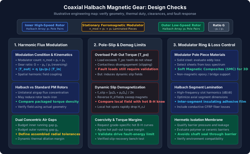
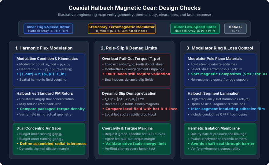
Figure 1: Engineering decision map, not a cross-sectional drawing or test result. Each design choice requires geometry-specific verification.
Governing Harmonic Coupling Equations
The modulator changes the air-gap permeance, producing spatial harmonics from the inner rotor field. With inner-field harmonic order m and modulation order k, the signed harmonic order is:
h_m,k = m * p1 + k * n_mod
pole-pair count of that harmonic = abs(h_m,k)
Omega_m,k = (m * p1 * Omega_1 + k * n_mod * Omega_mod) / h_m,k
The velocity expression applies to a nonzero signed order. Keeping its sign matters because it describes the harmonic's rotation direction. For the commonly used m = 1, k = -1 coupling, a stationary ring gives:
n_mod = p1 + p2
p1 * Omega_1 + p2 * Omega_2 = 0
G = Omega_1 / Omega_2 = -p2 / p1
Both shaft velocities use the same positive angular direction. The negative ratio means the rotors counter-rotate. For torque magnitudes under steady motoring operation:
abs(T_out) = eta * (p2 / p1) * abs(T_in)Here eta is measured or modeled whole-assembly efficiency at the stated operating point. It includes the losses appropriate to the agreed system boundary. Do not insert a generic efficiency or mix signed external shaft torques with torque magnitudes. The stationary modulator support also carries reaction torque and needs a structural load path.
The Halbach-array coaxial gear study by Jian and Chau is a topology-specific starting reference. For analytical torque calculation and transient behavior, Tzouganakis and colleagues' 2024 model compares its two-dimensional predictions with finite element analysis. That comparison is model-validation evidence, not a qualification test for a supplied gearbox.
What Halbach Arrays Change
Progressively oriented magnet segments can concentrate flux toward the working gap and reduce flux on the opposite side. The magnetization sequence must be designed for the chosen cylindrical field, pole count, and inward- or outward-facing working surface. A single fixed block-angle recipe does not define every cylindrical Halbach rotor.
Useful field concentration may reduce the required back iron, but finite segmentation, end leakage, structural sleeves, and manufacturing errors remain. Halbach construction does not guarantee higher packaged torque density, a particular efficiency, zero rotor mass penalty, or negligible stray field. Compare equal envelopes and equal thermal duty, including carriers, bearings, cooling, and containment. Review Halbach ring capabilities when defining which magnetic components belong in the supplier's scope.
2. Quantitative Architecture Comparison: Define the Measurement Boundary
A procurement comparison needs consistent definitions before numerical ranking. Active magnetic volume excludes structures that the installed product still needs; continuous torque depends on cooling and temperature; peak pull-out torque is a different rating. Quoted efficiency at one favorable speed cannot describe a complete duty cycle.
Use the following comparison matrix to request evidence across a Halbach magnetic gear, a conventional PM magnetic gear, a planetary reducer, and a strain-wave reducer. It intentionally avoids unsupported universal performance ranges.
| Selection metric | Coaxial Halbach magnetic gear | Mechanical reducer comparison | Evidence to request |
|---|---|---|---|
| Continuous output torque | Limited by thermal, magnetic, and mechanical margins | Limited by tooth, bearing, lubricant, and thermal ratings | Torque-speed-temperature map at the same duty |
| Pull-out or overload torque | Magnetic synchronism can be lost | Overload limits depend on reducer construction | Peak duration, inertia, recovery, and damage criteria |
| Packaged torque density | Include both rotors, carrier, bearings, and housing | Include lubricant and required accessories | Identical volume and mass definitions |
| Efficiency | Magnet, steel, sleeve, bearing, and windage losses remain | Mesh, seal, bearing, and lubricant losses remain | Input/output power over the operating map |
| Backlash and compliance | No tooth-clearance backlash; finite magnetic deflection | Backlash and compliance depend on model and preload | Loaded angle-error and stiffness curves |
| Lubrication and maintenance | Magnetic interface needs no tooth lubricant; bearings may need it | Follow the selected reducer's service requirements | Assembly maintenance schedule and bearing strategy |
| Noise and vibration | Torque ripple, bearings, and structural modes remain | Tooth excitation and bearing modes need assessment | Same speed, load, mounting, and measurement distance |
| Hermetic separation | Possible with a designed stationary barrier | Depends on the wider drive and sealing arrangement | Pressure, leak, corrosion, and barrier-loss tests |
| Cost and availability | Custom magnets, fixtures, and validation affect cost | Standard catalog options may shorten procurement | Same quantity, scope, lead time, and acceptance plan |
Choose magnetic gearing when contactless torque transfer, overload decoupling, or a stationary containment barrier solves a concrete system problem. Favor a catalog mechanical reducer when its stiffness, envelope, availability, and proven duty rating already meet the requirement economically. Neither architecture removes the need for failure analysis.
For magnetic gear development research, see Rasmussen and colleagues' development paper. Its existence supports investigating practical magnetic gearing; it does not establish interchangeability with any catalog mechanical reducer.
3. The Pole-Slip Mechanism and Demagnetization Safeguards
Pull-Out Torque Is an Operating Boundary
Define the electrical load angle using mechanical rotor positions measured in the same direction:
psi = p1 * theta_1 + p2 * theta_2
abs(T_out) approximately follows T_po,out * abs(sin(psi))
This is a dominant-harmonic approximation, not the complete torque-ripple waveform. T_po,out is the output-side pull-out torque at the stated magnet temperature and geometry. Dynamic excitation can cause loss of synchronism even when a static torque comparison appears acceptable. Load inertia, acceleration, torsional oscillation, and control behavior all matter.
For the illustrative combination p1 = 4, p2 = 17, the ring has 21 pole pieces and the signed speed ratio is -4.25. An input at 3,000 rpm gives a synchronous output near -706 rpm. If a hypothetical output rating is 40 N·m and an engineer selects a preliminary pull-out factor of 1.5, the required hot pull-out torque is 60 N·m. That factor is an example assumption; the actual requirement must cover the specified transient duty and uncertainties.
Calculate Slip from Electrical Phase Mismatch
The fundamental coupling phase-slip frequency is:
f_slip = abs(p1 * Omega_1 + p2 * Omega_2) / (2 * pi)Angular velocities here are in radians per second. At synchronous speed the expression is zero. With the example's outer rotor locked and the input still at 3,000 rpm, it becomes 4 * 50 = 200 Hz. This is the fundamental coupling mismatch, not a complete spectrum of local magnet or steel excitation. Modulator passage and higher spatial harmonics can produce additional frequencies that require transient electromagnetic analysis.
Pole slip avoids a contacting gear-tooth fracture mechanism, but it is not automatically harmless. A jam can excite shaft loads, produce oscillatory torque, heat conductive parts, and prevent controlled recovery. Resynchronization after the obstruction clears depends on the load and controls; it should not be assumed.
Demagnetization Requires a Local, Temperature-Dependent Check
Evaluate the opposing field along each magnet segment's magnetization direction over the full slip cycle. Compare the local operating point with the supplier's temperature-dependent demagnetization curves and knee behavior. Room-temperature intrinsic coercivity H_cJ alone is not a safe operating boundary: irreversible loss can begin before the field reaches that intercept, depending on the grade and temperature.
High-coercivity NdFeB or SmCo may be suitable, but a grade suffix or advertised maximum working temperature does not prove survival. Obtain material curves, magnetization-direction tolerances, and the predicted hot-spot temperature. Recalculate after changing magnet thickness, segmentation, cooling, or gap geometry.
Specify slip detection using the phase mismatch or speed residual rather than dividing one measured speed by another near standstill. Establish trip thresholds, filtering, maximum fault energy, coast-down behavior, and restart conditions from the transient model and a controlled test. No universal millisecond trip time or seconds-long stall allowance is justified without thermal and mechanical evidence.
4. Modulator Pole Piece Sizing and Loss Mitigation
The condition n_mod = p1 + p2 determines count, not tooth width, radial depth, or axial length. Pole pieces need enough magnetic area to avoid excessive saturation while leaving room for structural support and the two working gaps.
A Reproducible Preliminary Geometry Example
For an illustrative modulator mean radius of 50 mm and 21 pieces, calculate the circumferential pitch and choose a trial tooth arc fraction alpha:
pitch angle = 360 / 21 = 17.14 degrees
circumferential pitch = 2 * pi * 50 / 21 = 14.96 mm
trial alpha = 0.50
trial tooth arc width at mean radius = 0.50 * 14.96 = 7.48 mm
That width is an initial modeling input, not an optimum. At different radii the arc width changes. The tooth's narrowest magnetic section, fringing, bridge leakage, and local flux direction determine its actual saturation behavior.
As a separate screening calculation, suppose an assumed peak tooth flux is 0.20 mWb and the designer selects a trial average steel flux density of 1.5 T. Then A_steel >= Phi / B_trial = 133 mm². With an assumed lamination stacking factor of 0.95, gross section area must be at least 140 mm². If that section is approximated by 7.48 mm tooth width times axial length, the arithmetic gives about 18.8 mm axial length.
The assumed flux is not predicted by the pole count. Obtain it from a field solution, inspect local peaks and end leakage, and iterate the geometry. This simple area calculation cannot certify pull-out torque or temperature. Sweep tooth arc fraction and radial depth, then compare torque ripple, loss, structural stress, and hot pull-out torque across candidate designs.
Modulator Material Trade-Off Matrix
For comparable flux waveforms and within the classical thin-sheet approximation, eddy-current loss density scales roughly with d² * f² * B_pk² / rho, where d is the dimension limiting the current loop and rho is resistivity. Real loss also includes hysteresis, excess loss, harmonics, and manufacturing damage. Use measured material loss data and electromagnetic models to select a lamination thickness.
| Construction choice | Magnetic consideration | Loss consideration | Manufacturing or validation question |
|---|---|---|---|
| Thin electrical-steel laminations | Check grade-specific B-H behavior and stacking factor | Thin insulated sheets restrict current loops | Can cutting and bonding preserve insulation and flatness? |
| Thicker electrical-steel laminations | May simplify handling | Compare actual loss at the excitation spectrum | Is the thermal benefit of thinner sheets worth the cost? |
| Soft magnetic composite | Useful for some three-dimensional flux paths | Distributed insulation changes eddy behavior | Are permeability, loss, and mechanical strength acceptable? |
| Solid low-carbon steel | Can carry flux but is electrically conductive | Unsegmented paths may create substantial loss | Is low-frequency duty supported by a thermal calculation? |
| Bridged lamination ring | Bridges may divert useful flux | Local saturation and loss need modeling | Does bridge strength justify the leakage penalty? |
| Discrete laminated teeth in a cage | Reduces one bridge-leakage path | Conductive cage material may add losses | How are teeth positioned and retained under reaction torque? |
A solid steel prototype is not automatically disqualified above a universal rotational speed, and a laminated design is not automatically thermally safe. Insulating coatings, lamination orientation, conductive fasteners, and end plates can change the loss path. Ask the supplier to state how the stack is held without unintentionally shorting insulated sheets.
Rotor Eddy Losses Need Their Own Budget
Even under synchronous coupling, each rotor can experience asynchronous spatial harmonics. Axial and circumferential magnet segmentation can interrupt eddy-current paths, provided interfaces remain electrically insulated. Optimize segment dimensions against the calculated harmonic spectrum; there is no universally correct block length.
Include sleeves, hubs, shields, and containment cans in the loss model. Carbon-fiber composites are electrically conductive along fibers; treating every CFRP sleeve as an electrical insulator can underpredict heating. Metallic sleeves require their own electromagnetic and thermal assessment. Ceramic or polymer barriers avoid metallic current paths, but pressure, permeability, chemical compatibility, creep, and sealing still govern their suitability.
If the loss model or component scope is unresolved, use the RFQ contact page to request a scoped review with the pole combination, geometry assumptions, and duty cycle attached. Describe which analysis and acceptance records are required before ordering tooling.
5. Dual Concentric Air-Gap Tolerances and Rotor Retention
The inner working gap lies between the inner rotor and modulator; the outer gap lies between the modulator and outer rotor. Distinguish physical running clearance from effective magnetic separation, which also includes sleeves, coatings, adhesive layers, and any containment wall.
Budget each radial clearance separately:
g_min = g_nominal - manufacturing allowance - bearing motion
        - differential thermal closure - centrifugal closure
        - structural deflection allowance
All allowances must use a consistent radial convention. For an illustrative inner gap of 0.80 mm, allocations of 0.08 mm, 0.05 mm, 0.12 mm, and 0.05 mm for manufacturing, bearing motion, combined thermal/centrifugal closure, and structural deflection leave 0.50 mm. The arithmetic shows the remaining clearance; it does not establish that this clearance is sufficient.
Check the outer gap independently and avoid counting the same displacement twice. Total indicated runout is not automatically a one-sided radial displacement. The drawing must define the datum axis, assembled measurement condition, axial measurement positions, temperature, and interpretation of each tolerance.
Increasing either effective magnetic gap generally reduces useful coupling, but a single inverse-square law or percentage torque penalty cannot describe every coaxial gear. Compare worst-case geometry variants in the field model. Inspect local eccentricity and unbalanced magnetic pull as well as the average gap.
Rotor retention depends on radius, speed, magnet mass, fit, temperature, and material properties. Sleeve thickness, winding tension, interference, and allowable stress require a structural calculation; a generic RPM threshold does not select them. Balance the final assembled rotor to a project-agreed procedure and grade, then verify vibration and clearance across the speed range. Review manufacturing and assembly processes when agreeing inspection ownership and records.
6. Sourcing and Engineering RFQ Validation Checklist
Use this checklist to make quotations comparable. A missing item should become an explicit assumption or an unresolved requirement, rather than an implied guarantee.
- 1. Topology and direction: State
p1,p2,n_mod, the fixed member, rotation directions, and required ratio. Identify physical block count separately. - 2. Duty and torque boundary: Separate continuous, transient, and hot pull-out torque. Include speed, inertia, acceleration, cooling, and the selected design margin.
- 3. Magnet evidence: Request grade-specific temperature-dependent demagnetization curves and a local opposing-field assessment during normal operation and faults.
- 4. Pole-piece geometry: Specify pitch, tooth arc, radial depth, stack length, stacking factor, material curve, and saturation results.
- 5. Modulator support: Require a reaction-torque load path, bridge or cage analysis, tooth-retention method, and insulation details.
- 6. Loss allocation: Separate magnet, modulator, sleeve, containment, bearing, and windage losses at representative duty points.
- 7. Two-gap inspection: Define assembled datums, radial tolerances, thermal extremes, minimum running clearances, and effective magnetic gaps.
- 8. Rotor retention: Request stress, fit, fatigue, and overspeed evidence for the selected sleeve and adhesive system.
- 9. Balance and environment: Agree final-assembly balancing, vibration limits, coatings, bearing service, and any pressure or leak qualification.
- 10. Fault acceptance: Define detection and shutdown behavior, bounded slip energy, restart conditions, and pre/post-test pull-out torque acceptance criteria.
Agree test instrumentation and uncertainty before placing an order. Measure input and output power at defined steady points, record magnet or validated proxy temperatures, and explain how losses are separated. A fault test should use protective limits established beforehand, not an arbitrary prolonged stall.
7. Frequently Asked Questions
Q1: Can a coaxial magnetic gear achieve any arbitrary ratio, such as 100:1?
A: The pole-count relation permits combinations such as p1 = 1, p2 = 100, n_mod = 101, but geometric feasibility depends on diameter, pole pitch, gaps, segmentation, and losses. High ratio alone does not prove useful torque density. Compare single-stage and multistage arrangements within the actual envelope; no universal optimum ratio applies to all sizes.
Q2: Does a Halbach magnetic gear provide hermetic containment?
A: A stationary barrier can separate environments without a rotating shaft seal through that barrier. The complete enclosure still needs pressure, leak, chemical, permeation, and thermal qualification. Added barrier thickness changes magnetic separation, and conductive barriers can create eddy losses. Contactless transmission alone does not certify a leak-free assembly.
Q3: What happens if the outer rotor locks while the input is running?
A: The gear may lose synchronism and produce oscillatory torque while conductive components heat. For p1 = 4 and 3,000 rpm input, the locked-output fundamental phase-slip frequency is 200 Hz. Stop or limit the drive according to a validated fault-energy budget, then verify that restart is safe. Slip does not guarantee mechanical or magnetic survival.
Q4: Do non-magnetic housings shield external magnetic fields?
A: Non-magnetic aluminum or austenitic stainless steel does not automatically provide effective shielding against static magnetic fields. Halbach field concentration can reduce leakage, but end effects and assembly errors remain. Specify a measured stray-field map at defined distances and loads. Assess any proposed shielding for saturation, added mass, and losses.
Q5: Will the magnetic gear cost less over its lifetime?
A: That depends on acquisition, integration, validation, bearing service, cooling, downtime, repairability, and volume. Removing tooth lubrication can help a particular installation, but it does not remove every maintenance task. Compare documented lifecycle assumptions and replacement lead times instead of assuming a universal payback period or maintenance-free lifetime.
Q6: Does magnetic compliance cause hunting or resonance?
A: It can. In the dominant-harmonic model, torque varies sinusoidally with electrical load angle, so effective torsional stiffness falls as pull-out is approached. Rotor inertias, damping, shaft compliance, and controller tuning determine the dynamic response. Calculate stiffness using a clearly defined mechanical coordinate and validate the coupled drivetrain response over its operating range.
8. Preparing a Scoped Halbach Magnetic Gear Inquiry
For an initial discussion, provide the required ratio, speed range, continuous and peak output torque, envelope, ambient and cooling conditions, operating environment, and expected annual quantity. Include the load inertia and fault scenario if overload decoupling is a design objective. These inputs help distinguish a magnetic-component inquiry from a complete gearbox development project.
Use the magnetic gear sourcing guide to check the pole combination, then contact Halbach Magnet about your RFQ. Ask the supplier to confirm responsibility for electromagnetic design, rotor mechanics, bearings, controls, and validation in writing. Specify which deliverables are preliminary estimates and which become contractual acceptance criteria.
Sources and References
These references provide topology, development, and modeling context. The worked dimensions, assumed margins, and procurement framework above are illustrative engineering analysis; they are not reported test results from these papers or product guarantees.
- Jian, L., and Chau, K. T. (2010). A Coaxial Magnetic Gear With Halbach Permanent-Magnet Arrays. IEEE Transactions on Energy Conversion, 25(2), 319–328. Reference for the Halbach coaxial topology.
- Tzouganakis, P., Gakos, V., Kalligeros, C., et al. (2024). Torque Calculation and Dynamical Response in Halbach Array Coaxial Magnetic Gears through a Novel Analytical 2D Model. Computation, 12(5), 88. Analytical model with FEA comparison and transient-slippage case studies; not an assembly qualification report.
- Rasmussen, P. O., Andersen, T. O., Jørgensen, F. T., and Nielsen, O. (2005). Development of a High-Performance Magnetic Gear. IEEE Transactions on Industry Applications, 41(3), 764–770. Magnetic gear development reference; not a universal performance specification.
Author

Categories
More Posts
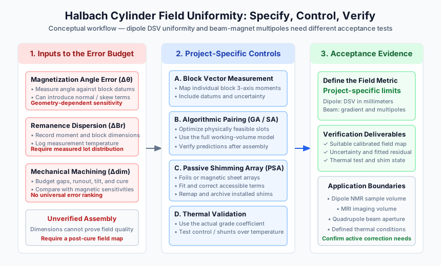
Halbach Cylinder Field Uniformity: Specifying Angular Tolerances, Block Pairing, and Passive Shimming for NMR and Beam Optics
Specify Halbach cylinder field uniformity with block pairing, angular tolerance and shimming checks for NMR and beam optics. Prepare your engineering RFQ.

Halbach Array Manufacturing: Cost vs. Yield in Assembly-First vs. Magnetize-Later Techniques
Compare Halbach array assembly-first vs magnetize-later manufacturing by cost, yield, grade limits, supplier checks, and RFQ timing.
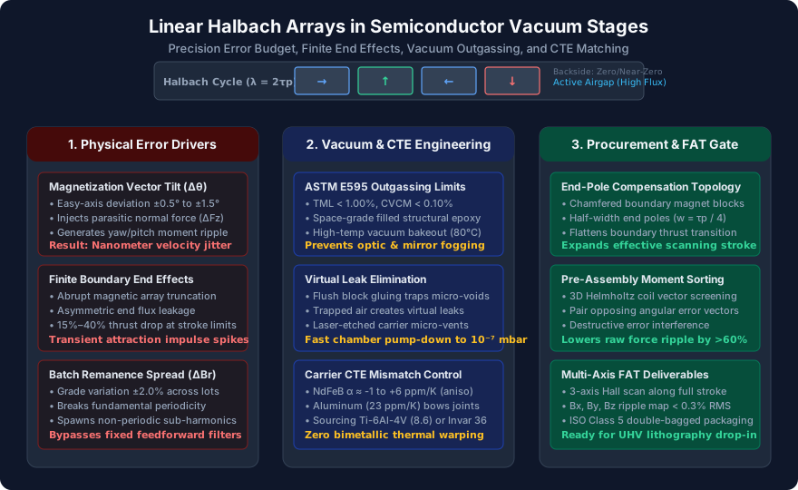
Linear Halbach Arrays for Vacuum Wafer Stages: Mitigating Force Ripple, Boundary End Effects, and CTE Mismatch in Precision Motion Systems
Specify linear Halbach arrays for vacuum wafer stages: mitigate force ripple, boundary end effects, ASTM E595 outgassing, and CTE carrier mismatch in your RFQ.