
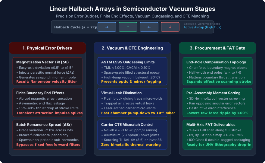
Linear Halbach Arrays for Vacuum Wafer Stages: Mitigating Force Ripple, Boundary End Effects, and CTE Mismatch in Precision Motion Systems
Specify linear Halbach arrays for vacuum wafer stages: mitigate force ripple, boundary end effects, ASTM E595 outgassing, and CTE carrier mismatch in your RFQ.
In semiconductor photolithography, electron-beam inspection, and extreme-vacuum metrology stages, positioning budgets are measured in sub-nanometer increments. Delivering consistent acceleration exceeding 10g while preserving steady-state scanning jitter below 0.5 nm 3-sigma requires an actuator with maximum force density and zero cogging. For these coreless, iron-free planar and linear motion systems, linear Halbach permanent magnet arrays have become the industry baseline. By rotating the magnetization easy axis across discrete permanent magnet segments, a linear Halbach array concentrates magnetic flux on the working airgap side facing the motor coils while canceling it on the back side.
However, moving from textbook 2D infinite-boundary equations to a manufactured vacuum-grade linear Halbach track introduces severe multi-physics challenges. An assembly that passes a Coordinate Measuring Machine (CMM) inspection with ±0.01 mm mechanical accuracy can still fail catastrophically inside a vacuum chamber.
Why? Because mechanical tolerance alone does not guarantee magnetic field periodicity. Magnetization vector angular tilts ( to ) inject parasitic normal force ripple and pitching moments into the stage. Abrupt array truncations at stroke ends generate boundary "end effects" that trigger severe velocity transients during turnaround. Trapped air pockets between flush-glued magnet blocks produce stubborn "virtual leaks" that stall vacuum pump-down. And under the thermal dissipation of moving coils in a vacuum, the extreme coefficient of thermal expansion (CTE) mismatch between anisotropic NdFeB magnets and aluminum backplates causes bimetallic thermal warping that distorts the stage airgap.
This guide provides motion systems architects, mechatronics engineers, and semiconductor equipment procurement teams with an actionable engineering framework to model, specify, and procure linear Halbach arrays for vacuum wafer stages without unexpected force ripple or vacuum qualification failures.
Need an engineering review for a custom linear Halbach track? Discuss your stroke limits, airgap constraints, and vacuum requirements with our technical team before finalizing drawing tolerances.
Scope and review date: Published and reviewed October 29, 2026, for precision motion engineers and technical procurement specialists sourcing linear and planar Halbach magnet assemblies. This document addresses both single-sided and double-sided linear tracks operating in ambient cleanrooms (ISO Class 4 / Class 100) and High Vacuum / Ultra-High Vacuum (HV/UHV down to ).
The Electromagnetic Foundation: Ironless High-Force Density
To understand where manufacturing imperfections corrupt motion fidelity, we must first review the ideal analytical model of a linear Halbach array.
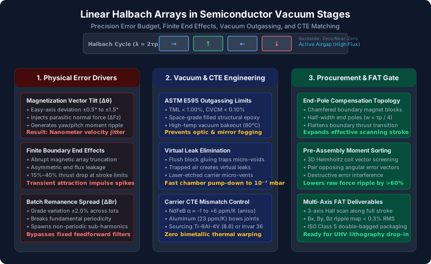 Figure 1: The three pillars of precision linear Halbach engineering: controlling electromagnetic error drivers, engineering vacuum and thermal stability, and executing multi-axis factory acceptance testing.
In a standard ironless linear motor, copper coil windings travel across a stationary permanent magnet track (or vice-versa). Traditional magnet tracks require heavy laminated silicon-steel or solid iron backplates to complete the magnetic flux return path. In dynamic wafer scanners, this back-iron adds excessive moving mass, increases settling times, and creates massive normal magnetic attraction forces (often 5 to 10 times the peak thrust force) that overload the stage's air bearings or magnetic levitation guides.
A linear Halbach array resolves this by arranging discrete magnet blocks with a spatial phase shift of ( blocks per magnetic wavelength , where is the pole pitch). On the active airgap side, the vertical and horizontal magnetization components add constructively in phase. On the back side, they oppose each other in antiphase.
Airgap Flux Density Formulation
For an ideal linear array of height and pole pitch , the fundamental spatial wavenumber is . The peak fundamental airgap flux density at a distance above the array active surface is given by:
Where:
- is the magnetic remanence of the sintered magnet grade (typically 1.30 T to 1.48 T for N45–N52 NdFeB).
- is the number of magnet segments per electrical period (commonly for a Halbach array, or for a quasi-Halbach array).
- is the magnet segment height in the direction of the working airgap.
- is the physical clearance distance (airgap) from the magnet array surface to the center of the coil conductors.
The term represents the discrete segmentation factor:
- For (4 blocks per pole pair, rotation): the segmentation factor is .
- For (8 blocks per pole pair, rotation): the segmentation factor rises to .
While an 8-block topology yields approximately 8.2% higher fundamental flux density than a 4-block array for identical physical envelopes, it doubles the number of glued joints, doubles the potential angular error interfaces, and significantly increases manufacturing costs.
The Myth of "Zero Stray Field"
A widespread misconception among procurement teams is that a linear Halbach array has zero magnetic flux leakage on its inactive rear face. In an ideal continuous Halbach cylinder, external flux cancels completely. However, in a discrete flat linear array, perfect cancellation only occurs for the fundamental spatial harmonic.
Higher-order space harmonics (notably the -th harmonic, such as the 3rd and 5th harmonics in an array) leak out of the back surface with an amplitude of approximately 2% to 6% of the front-side peak field. If this inactive face is bolted directly to an unshielded structural carrier made of standard 400-series stainless steel or structural carbon steel, parasitic magnetic attraction and eddy currents will develop during high-acceleration motion. The backing structure must be non-magnetic (permeability ) or separated by an engineered non-magnetic buffer gap.
Physical Mechanisms of Force Ripple: Why Micron Tolerances Fail
In wafer scanning, the stage moves through an exposure stroke where the scanning velocity must maintain a stability error within parts-per-million (). Any spatial perturbation in the motor thrust force creates velocity jitter, forcing the servo controller to inject compensating current commands that induce high-frequency structural vibrations.
In ironless linear motors, there are no stator iron teeth, eliminating classical slotting cogging. Therefore, all periodic force ripples originate from imperfections within the magnet track itself and their interaction with the coil current distribution.
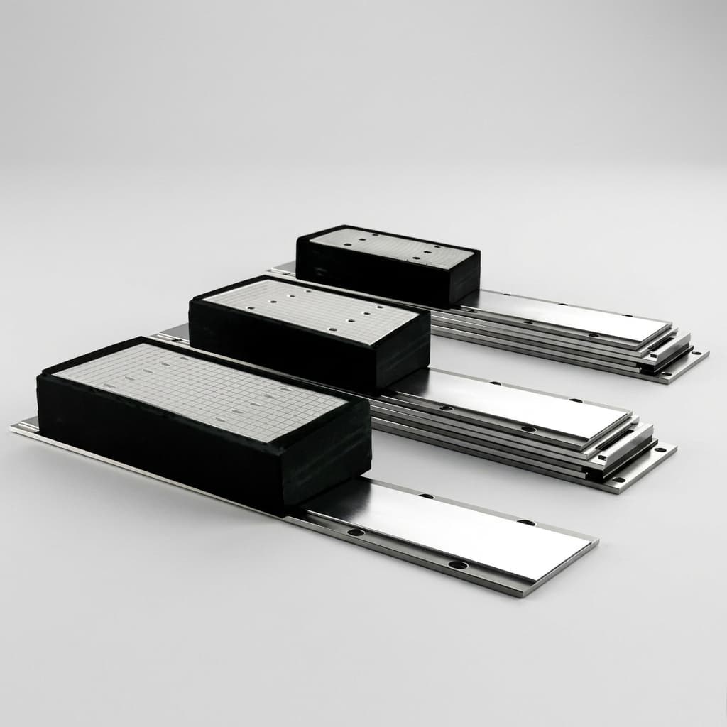 Figure 2: Precision planar Halbach track undergoing multi-axis coordinate and flux density verification. Sintered magnet blocks must be individually sorted to cancel out easy-axis deviations prior to bonding.
1. Spatial Discretization Harmonics
Because the magnetization in commercial linear arrays rotates in discrete steps rather than a continuous mathematical distribution, the resulting airgap magnetic field contains non-negligible spatial harmonics:
For an array, the dominant parasitic harmonic is the 5th spatial harmonic, followed by the 9th harmonic. When interacting with three-phase distributed coil windings, the 5th and 7th spatial harmonics produce a 6th-order electrical force ripple.
To suppress this harmonic without increasing segment count to , precision manufacturers employ magnetic pole pitch optimization or skewing of the magnet blocks by an angle , where is the block width.
2. Easy-Axis Angular Deviation ()
When anisotropic sintered NdFeB blocks are pressed in an orienting magnetic field during powder metallurgy sintering, the crystallographic c-axis alignment is never perfectly uniform. Commercial magnet grades carry an easy-axis angular tolerance between and relative to their geometric cutting datums.
Consider a longitudinal block whose magnetization vector should be purely horizontal (). If the actual vector is tilted by an angle toward the vertical axis, a parasitic vertical flux component emerges:
At and (), this parasitic vertical field is:
When the motor phase current flows to produce horizontal thrust , it simultaneously interacts with to produce a parasitic vertical normal force ripple () and an associated pitching moment ():
In a wafer stage with 1,000 N peak thrust, an uncontrolled angular dispersion can produce dynamic normal force pulsations of 15 N to 25 N. This lifts or presses down on the aerostatic or magnetic bearings, exciting mechanical resonances between 300 Hz and 1.2 kHz and directly degrading focus and overlay accuracy.
3. Lot-to-Lot Remanence Spread ()
Even within the same production run, chemical composition fluctuations and sintering temperature gradients across the vacuum furnace cause a remanence dispersion of to .
If high- blocks and low- blocks are placed randomly along the linear track, the fundamental periodicity of the magnetic field breaks down. This non-periodic perturbation generates sub-harmonic force ripples (frequencies lower than the fundamental pole passing frequency).
Because feedforward servo controllers rely on spatial lookup tables mapped to the nominal pole pitch , non-periodic sub-harmonics cannot be eliminated by fixed harmonic notch filters.
Manufacturing Mitigation: Every single magnet block must undergo 3D magnetic moment vector characterization inside a calibrated Helmholtz coil fixture before assembly. A combinatorial algorithm (such as a genetic algorithm or simulated annealing) then pairs blocks with complementary error vectors ( paired with , and paired with ) along opposing positions in the track. This destructive interference cancels out spatial error harmonics by more than 60% before any physical assembly begins.
Finite Boundary End Effects in Motion Stages
Standard electromagnetic textbook equations assume an infinitely long periodic array. However, a wafer stage operates over a physical track of finite length (typically 350 mm to 800 mm).
At the physical ends of the track, the periodic boundary condition is truncated abruptly. This creates a severe electromagnetic disturbance known as the boundary end effect.
The Physics of Array Truncation
In an infinitely periodic Halbach array, the magnetic flux from each vertical pole finds a low-reluctance return path through the adjacent horizontal magnet blocks. At the terminal block of a finite track, this return path is severed.
Flux leaks out of the array edges into the surrounding free space, causing two critical performance anomalies:
- Asymmetric Thrust Drop: The usable peak airgap flux density begins dropping between and before the physical end of the track. If the coil package approaches this region, motor thrust drops by 15% to 40% for the same input current.
- Normal Force Impulse Spikes: As the coil enters or exits the boundary zone, the asymmetrical fringe field produces a sudden impulse in vertical attraction or repulsion. During high-speed turnaround maneuvers at the end of each scanning line, this transient impulse shocks the stage guidance bearings.
Engineering Solutions to Suppress End Effects
Motion systems engineers use three proven structural techniques to eliminate end-effect disturbances:
A. Standard Truncated Array (Severe end flux distortion & normal force spikes)
[ → ] [ ↑ ] [ ← ] [ ↓ ] ... [ → ] [ ↑ ] [ ← ] [ ↓ ] [END TRUNCATION]

B. Half-Width Auxiliary End Poles (Symmetric flux closure)
[ w=τp/4 ] [ → ] [ ↑ ] [ ← ] [ ↓ ] ... [ → ] [ ↑ ] [ ← ] [ ↓ ] [ w=τp/4 ]

C. 45° Chamfered Boundary Magnet Blocks (Tapered spatial permeance transition)
[/ Chamfer /] [ ↑ ] [ ← ] [ ↓ ] ... [ → ] [ ↑ ] [ ← ] [\ Chamfer \]- Auxiliary Half-Width End Poles (): Terminating the track with a magnet block having half the standard pole width and half the standard magnetic moment forces the edge flux lines to loop back locally, restoring vertical symmetry to the boundary field.
- Chamfered Boundary Blocks: As demonstrated by Liu et al. (2024), cutting a to chamfer on the outermost magnet block tapers the airgap permeance transition gradually, suppressing transient boundary force ripple by over 45% compared to blunt rectangular terminations.
- Over-Travel Track Sizing: Sizing the physical magnet track to extend beyond the active exposure stroke by at least on both ends. This ensures the moving coil pack never enters the non-linear fringe zone during active wafer exposure.
Vacuum and Cleanroom Engineering: ASTM E595, Virtual Leaks, and Outgassing
Semiconductor wafer processing takes place in controlled environments ranging from ISO Class 1 mini-environments down to High Vacuum () and Ultra-High Vacuum () for extreme ultraviolet (EUV) lithography and e-beam wafer inspection tools.
In these environments, a linear Halbach array is not just a magnetic circuit—it is a critical vacuum component subject to stringent outgassing and particle shedding standards.
1. Structural Adhesive Outgassing (ASTM E595 & NASA SP-R-0022A)
Permanent magnet blocks in a linear Halbach array repel each other with extreme shear forces. Locking them onto a structural baseplate requires high-shear structural adhesives. However, standard commercial epoxies contain low-molecular-weight reactive diluents, plasticizers, and amine curing agents that volatize rapidly in a vacuum.
Under high vacuum, outgassed organic molecules condense onto sensitive optical surfaces—such as EUV projection mirrors, beam splitters, and laser interferometer retroreflectors—forming an irreversible carbonaceous contamination film.
To prevent this, all bonding materials used in the array must be certified to ASTM E595 (tested at for 24 hours at ):
- Total Mass Loss (TML): Must be strictly (target for semiconductor tools).
- Collected Volatile Condensable Material (CVCM): Must be strictly (target ).
- Water Vapor Recovered (WVR): Recorded to differentiate moisture absorption from organic decomposition.
Qualified space- and vacuum-grade epoxies (such as filled high-glass-transition-temperature bisphenol-A/epichlorohydrin systems or cyanate esters) must be cured under precise thermal ramp profiles followed by an 80°C to 100°C vacuum bakeout for 24 to 48 hours.
2. The Danger of "Virtual Leaks"
A virtual leak occurs when gas becomes trapped in a closed cavity inside a vacuum system and slowly seeps out through microscopic crevices into the chamber. It mimics a real wall leak, preventing the vacuum pumps from ever reaching base pressure.
In a linear Halbach array, virtual leaks are routinely created by:
- Flush block-to-block bonding: Gluing flat magnet faces directly against one another without an escape path traps pockets of air and residual cleaning solvents.
- Blind tapped holes: Mounting screws installed in blind holes on the backing plate trap pockets of air beneath the screw tip.
Design Rules for Vacuum Halbach Arrays:
- Micro-Venting Channels: Machine fine venting grooves (0.3 mm wide × 0.15 mm deep) along the non-functional bottom mating face of the carrier plate or introduce a 0.2 mm chamfer on magnet bottom edges to provide an open vacuum conductance pathway.
- Through-Vented Fasteners: All assembly bolts must feature a central longitudinal through-hole (vented screws per DIN 912-V) to vent trapped air pockets from thread roots.
- No Unvented Enclosures: Encapsulation covers or side retention rails must have clear venting slots.
3. Magnet Plating and Particle Control
Sintered NdFeB is a brittle powder metallurgy composite with an open grain boundary structure. If left uncoated, raw NdFeB continuously sheds microscopic sub-micron particles under dynamic vibration. In an ISO Class 4 cleanroom or vacuum wafer chamber, a single 100 nm ferromagnetic particle falling onto a wafer surface ruins a complete die pattern.
Standard electroplated bright nickel is unsuitable for semiconductor vacuum use because the electroplating brighteners create microscopic micro-cracks and internal tensile stress that flake off under thermal cycling.
Recommended Plating Systems:
- Electroless Nickel-Phosphorus (ENP, High-Phosphorus > 10.5% P): Amorphous, completely non-magnetic (), highly uniform thickness (15 µm to 25 µm) even on sharp corners, zero pinholes, and superior scratch resistance.
- Multi-Layer PVD Coating (TiN / Au): Physical Vapor Deposition of Titanium Nitride or pure Gold over an ENP underlayer. Provides zero outgassing, high chemical inertness, and passes 100% cross-hatch adhesion testing per ASTM D3359.
Thermal-Mechanical CTE Mismatch: Carrier Plate Selection and Warping
In an ambient electric motor, forced air or liquid cooling jackets remove heat efficiently. In a vacuum wafer stage, convective cooling is impossible.
Motor coils dissipate substantial Joule heating () during fast stepping maneuvers. While coil packs typically have integrated closed-loop cooling circuits, radiant and conductive heat transfer elevates the temperature of the adjacent magnet track by to above ambient.
Anisotropic Thermal Expansion of Sintered NdFeB
Sintered NdFeB does not expand isotropically. Because the tetragonal crystal lattice () expands differently along its crystallographic axes, the coefficient of thermal expansion (CTE, ) depends heavily on the magnetization direction:
- Parallel to Magnetization (): to (near zero, or even slightly negative thermal contraction!).
- Perpendicular to Magnetization (): to .
In a Halbach array, adjacent blocks have orthogonal magnetization vectors. One block expands horizontally while its neighbor contracts or remains dimensionally stable horizontally.
The Bimetallic Strip Catastrophe
If a 500 mm long Halbach array is bonded to a standard Aluminum 6061-T6 carrier plate (), a catastrophic thermal mismatch occurs.
Over a temperature rise of :
- The aluminum plate attempts to expand by:
- The NdFeB magnet track (average effective horizontal CTE ) only expands by:
The differential expansion () acts as a giant bimetallic strip. The assembly bows convexly toward the magnet face.
For a typical 15 mm thick aluminum plate, this thermal bowing introduces an out-of-flatness bow of 30 µm to 70 µm across the track length. In a wafer stage where the nominal mechanical airgap between moving coils and magnets is only , a 50 µm bow alters the airgap by 5%, causing severe spatial thrust gain variation and risking catastrophic mechanical rubbing inside the vacuum chamber. Furthermore, the massive interfacial shear stress exceeding 25 MPa will cause brittle delamination of the epoxy bond line.
Structural Carrier Material Comparison
To eliminate thermal distortion, the structural carrier material must be carefully selected to match the effective CTE of the magnet stack while maintaining high specific stiffness () and zero magnetic permeability.
| Carrier Material | CTE () | Density () | Young's Modulus () | Relative Permeability | Thermal Warping Risk | Vacuum / Sourcing Assessment |
|---|---|---|---|---|---|---|
| Aluminum 6061-T6 | Severe (>50 µm bow) | Unacceptable for precision vacuum stages without flexible flexure mounts | ||||
| Stainless Steel 316L | High (20–40 µm bow) | Heavy moving mass; cold work can induce slight ferromagnetism () | ||||
| Titanium Grade 5 (Ti-6Al-4V) | Low (5–12 µm bow) | Preferred baseline: High specific stiffness, completely non-magnetic, moderate CTE match | ||||
| Invar 36 (FeNi36) | Ferromagnetic () | Near-Zero (<2 µm bow) | Excellent CTE match, but ferromagnetic; requires non-magnetic standoff spacers | |||
| CFRP (Quasi-Isotropic Carbon Fiber) | Near-Zero (<3 µm bow) | Premium solution: Ultra-light moving mass, zero magnetic response, requires ASTM E595 resin qualification | ||||
| Silicon Carbide (Reaction-Bonded SiC) | Virtually Zero (<1 µm bow) | Extreme stiffness, perfect thermal match, brittle and high fabrication/grinding cost |
Engineering Recommendation: For stationary magnet tracks, Titanium Grade 5 offers the best balance of cost, non-magnetic cleanliness, and low thermal warping. For ultra-dynamic moving-magnet stages where moving mass must be minimized, CFRP backplates with cyanate ester outgassing-qualified resin provide the ultimate positioning performance.
Comprehensive Engineering Trade-Off Matrix
Engineering and procurement teams must evaluate their motion requirements against realistic manufacturing capabilities. Use this matrix to specify realistic tolerances and inspection gates in your RFQ:
| Application Profile | Stage Architecture | Target Airgap Flux & Uniformity | Tolerable Force Ripple () | Magnet Grade & Coating | Structural Carrier & Mounting | Vacuum / Cleanroom Class | Mandatory FAT Verification Deliverable |
|---|---|---|---|---|---|---|---|
| EUV Lithography Wafer Scanner | Moving-magnet 6-DOF planar maglev | , RMS ripple | N50SH / High-P Electroless Ni-P () + Au | CFRP or Reaction-Bonded SiC with laser-etched vents | High Vacuum (), ISO Class 1 | Multi-axis 3D Hall scan ( grid), ASTM E595 test report, laser interferometer flatness under thermal ramp | |
| DUV Immersion Wafer Stage | Moving-coil double-sided linear track | , RMS ripple | N52H / High-P ENP () | Titanium Grade 5 with through-vented DIN 912-V bolts | Cleanroom ISO Class 3 / 4 (Ambient pressure) | 3D Hall scan of thrust and cross-talk ; automated block pairing log | |
| E-Beam Wafer Defect Inspection | Vacuum linear stage, low magnetic stray field | , rear stray | Sm2Co17 (High temp / zero drift) or N48UH / TiN PVD | Invar 36 with non-magnetic ceramic isolator studs | Ultra-High Vacuum () | Chamber residual gas analysis (RGA) report, Helmholtz 3D vector angle deviation report () | |
| High-Throughput Die Bonder | Single-sided linear motor, high acceleration | , RMS ripple | N52 / Standard ENP () | Aluminum 6061-T6 with flexure mounting pads | Cleanroom ISO Class 6 | Point Hall probe scan at 5 discrete stroke positions; CMM dimensional inspection certificate | |
| Direct-Drive Reticle Mask Stage | Moving-coil single-sided linear Halbach | , RMS ripple | N45SH / High-P ENP () | Titanium Grade 5 carrier with auxiliary end poles | Cleanroom ISO Class 3 | End-effect boundary force curve; dynamic back-EMF waveform analysis report | |
| Scanning Electron Microscope (SEM) Stage | Miniature linear Halbach, sub-micron airgap | , RMS ripple | SmCo 30M / Electroless Ni-P () | Austenitic 316L (Annealed ) | High Vacuum () | Outgassing certificate, 3-axis magnetic center alignment report | |
| Advanced Packaging Optical Metrology | Long-stroke () linear modular track | , RMS ripple | N48H / Standard Ni-Cu-Ni () | Modular Aluminum 6061 base with interlocking joints | Cleanroom ISO Class 5 | Modular joint transition field map ( discontinuity at seams) | |
| Cryogenic Sample Positioning Stage | Ironless linear Halbach down to 77K | at 77K | High-coercivity N38EH (to resist cryogenic spin reorientation) | Titanium Grade 5 or Invar 36 with cryogenic-rated epoxy | Ultra-High Vacuum (, 77K) | Pre- and post-cryogenic cycling magnetic flux measurement, shear bond pull test coupon |
The Semiconductor Motion Stage Procurement & RFQ Checklist
When preparing an RFQ package or manufacturing drawing for a linear Halbach array, use this engineering checklist to ensure all electromagnetic, vacuum, and mechanical boundaries are explicitly defined:
- 1. Define the Magnetic Topology and Segmentation: Specify pole pitch , segment count per electrical period ( or ), magnet block dimensions, and chamfer dimensions. State whether skewed poles or auxiliary end poles are required.
- 2. Specify Active Working Airgap and Scan Volume: State the exact nominal airgap (e.g., ) and the 3D working envelope over which magnetic field metrics must be evaluated.
- 3. Set Magnetic Vector Angle Tolerances: Mandate that all individual sintered blocks have an easy-axis angular dispersion of (or ) relative to block datum faces, verified via 3D Helmholtz coil measurements.
- 4. Require Combinatorial Block Pairing: Require the supplier to provide the block sorting and placement algorithm records showing that opposing vector errors () and remanence deviations () are paired to cancel parasitic harmonic ripple.
- 5. Specify Boundary End-Effect Mitigation: Define whether the stroke limits require auxiliary half-width end magnets (), chamfered terminal blocks, or an over-travel track extension ().
- 6. Enforce Outgassing Limits (ASTM E595): For vacuum applications, mandate that the completed assembly (including bonding adhesives and edge encapsulants) meets and , backed by an accredited laboratory test report.
- 7. Mandate Virtual Leak Elimination: Specify venting channels on carrier mating surfaces, vented mounting screws (DIN 912-V), and zero unvented blind pockets in the assembly drawing.
- 8. Match Carrier CTE and Flatness: Select a carrier material (Ti-6Al-4V, CFRP, or Invar 36) compatible with the stage thermal envelope. Specify pre- and post-cure track flatness (e.g., over 500 mm).
- 9. Define Plating System and Cleanliness: Mandate High-Phosphorus Electroless Nickel (>10.5% P, non-magnetic, 15–20 µm) or PVD TiN/Au. Prohibit standard bright nickel. Require 100% tape adhesion verification per ASTM D3359.
- 10. Require Multi-Axis 3D Hall Scan FAT Deliverables: Require delivery of the raw 3D magnetic field scan dataset () measured at the operating airgap across the entire operational stroke, including RMS thrust ripple and cross-axis field limits.
- 11. Cleanroom Packaging and Shipping Protection: Specify ultrasonic solvent cleaning, double-bagging in nitrogen-purged antistatic vacuum pouches inside an ISO Class 5 cleanroom, and magnetic flux containment packaging for air freight.
Frequently Asked Questions (FAQ)
Q1: Why not simply increase the number of magnet blocks to 8 per period () to eliminate force ripple?
A: Moving from ( steps) to ( steps) increases theoretical fundamental airgap flux by ~8.2% and pushes the first significant spatial harmonic from the 5th out to the 9th harmonic. However, in physical manufacturing:
- It doubles the number of discrete magnet blocks and glued interfaces for a given track length.
- Each additional glued joint introduces adhesive thickness tolerance stackup ( per joint), increasing cumulative pitch error along a 500 mm track.
- As magnet width shrinks (e.g., from 8 mm to 4 mm), machining and grinding tolerances represent a larger percentage of total block volume, and easy-axis alignment dispersion tends to widen during sintering of small cross-sections.
- Manufacturing and inspection costs increase by 60% to 100%.
For most wafer stages, an optimized array with pre-assembly 3D Helmholtz moment sorting and auxiliary end poles achieves lower total force ripple than an unsorted array, at significantly lower cost and higher structural yield.
Q2: How can we tell if stage velocity jitter is caused by magnet array force ripple or by mechanical bearing runout?
A: Perform a spatial frequency analysis (FFT) of the stage following error or position jitter during a constant-velocity scan:
- Magnet Array Force Ripple: Appears as discrete spatial harmonics locked strictly to the magnetic pole pitch and its integer multiples (e.g., spatial frequencies corresponding to , , and ). If you change the scanning velocity, the time-domain frequency of the error changes proportionally (), but the spatial wavelength remains identical.
- Bearing or Guide Runout: Typically manifests as low-frequency mechanical undulations tied to bearing carriage recirculating ball/roller pitch, or fixed structural resonances (eigenfrequencies) that do not shift in frequency when scan velocity changes.
- Cross-Coupling Test: If normal force fluctuations () correlate directly with the three-phase coil commutation angle, the root cause is magnetic vector tilt () in the magnet track.
Q3: Why is high-phosphorus Electroless Nickel preferred over standard electrolytic nickel plating?
A: Standard electrolytic nickel uses electric current to deposit nickel ions from a chemical bath. This creates two fatal problems for semiconductor stages:
- Dog-Bone Effect: Electric field concentration deposits excessively thick plating on sharp magnet edges while leaving center recesses under-plated, destroying dimensional flatness.
- Ferromagnetic Response & Residual Stress: Electrolytic nickel is ferromagnetic (), distorting airgap flux, and possesses high internal tensile stress that causes plating micro-cracks under thermal cycling.
High-Phosphorus Electroless Nickel (ENP, >10.5% P) is deposited via an autocatalytic chemical reduction:
- It produces an absolutely uniform plating thickness across all surfaces, sharp edges, and blind corners.
- It is completely amorphous and non-magnetic (), ensuring zero distortion of the Halbach magnetic circuit.
- It has near-zero internal stress and superior corrosion resistance against cleanroom cleaning agents (such as isopropyl alcohol and mild acids).
Q4: Can we use NdFeB grade N52 in a high-vacuum chamber, or will it demagnetize during vacuum bakeout?
A: Standard grade N52 has an intrinsic coercivity () and a maximum continuous operating temperature rating of only . In an open magnetic circuit (where the magnet operates at an operating point or permeance coefficient ), subjecting standard N52 to an to vacuum bakeout will cause irreversible thermal demagnetization of 3% to 8%.
Recommendation: For vacuum wafer stages requiring vacuum bakeout:
- Specify high-temperature, high-coercivity grades: N50SH (, ) or N48UH (, ).
- The minor reduction in room-temperature remanence (~2% to 4% lower compared to N52) is far outweighed by complete immunity to irreversible thermal loss during vacuum bakeout up to .
Q5: How do we prevent magnetic attraction between the rear face of the linear Halbach array and a steel machine base?
A: Although a linear Halbach array heavily attenuates back-face flux, finite discretization harmonics () cause a residual stray field of 10 mT to 40 mT within 3 mm of the rear surface.
- Material Isolation: Mount the magnet track on a non-magnetic structural carrier plate (Titanium Grade 5, Aluminum, or Austenitic Stainless Steel) with a minimum thickness of .
- Magnetic Field Decay: Because the rear stray field decays exponentially with distance (), an engineered non-magnetic gap of to reduces the residual flux density entering a carbon-steel machine base to (negligible).
- Shielding Backing: If the stage envelope is extremely compact, a thin 0.5 mm soft magnetic foil (such as high-permeability Mu-Metal or pure iron) can be bonded to the outer side of a 2 mm non-magnetic spacer to safely shunt residual leakage without perturbing the front-face Halbach circuit.
Conclusion: Partnering with Halbach Magnet for Semiconductor Precision
Building linear Halbach arrays for semiconductor motion systems requires mastering the delicate intersection of sub-micron precision mechanics, multi-harmonic electromagnetic modeling, and high-vacuum materials science. A successful procurement program starts by abandoning simplistic 2D assumptions and replacing them with comprehensive specifications covering magnetic vector angular limits, auxiliary end-effect boundaries, low-outgassing ASTM E595 adhesives, and carrier CTE matching.
Accelerate Your Stage Development with Our Engineering Team
At Halbach Magnet, we specialize in the design, FEA simulation, precision EDM fabrication, cleanroom assembly, and multi-axis 3D mapping of high-grade linear and planar Halbach arrays:
- Explore our dedicated Linear Halbach Arrays Product Line for standard and custom motor tracks.
- Review our Precision Metrology & Cleanroom QC Capabilities to examine our 3-axis automated Hall scanning and Helmholtz moment sorting equipment.
- Partner with our multi-physics team through Custom Simulation & Prototyping Services to model force ripple, end effects, and thermal deformation before cutting metal.
Contact our engineering and procurement team with your stroke length, working airgap, target force ripple, and vacuum chamber specifications. We will review your tolerance budget, provide 3D field simulations, and deliver custom linear Halbach arrays qualified for drop-in semiconductor tool integration.
Sources & References
- D. L. Trumper, W.-J. Kim, and M. E. Williams, Design and analysis framework for linear permanent-magnet machines, IEEE Transactions on Industry Applications, Vol. 32, No. 2, pp. 371–379 (1996). DOI: https://doi.org/10.1109/28.491486.
- J. W. Jansen, C. M. M. van Lierop, E. A. Lomonova, and A. J. A. Vandenput, Modeling of Magnetically Levitated Planar Actuators With Finite Coreless Moving-Magnet Array, IEEE Transactions on Magnetics, Vol. 43, No. 1, pp. 15–25 (2007). DOI: https://doi.org/10.1109/TMAG.2006.886051.
- Kai Liu, Fuxiang Chen, Shuo Zhao, et al., Optimization of acceleration and force ripple of planar motor based on a chamfered magnet array considering coil end effect, Sensors and Actuators A: Physical, Vol. 369, 115119 (2024). DOI: https://doi.org/10.1016/j.sna.2024.115119.
- ASTM International, ASTM E595-15(2021): Standard Test Method for Total Mass Loss and Collected Volatile Condensable Materials from Outgassing in a Vacuum Environment, West Conshohocken, PA (2021). URL: https://www.astm.org/e0595-15r21.html.
- NASA Outgassing Data for Spacecraft Materials, NASA Reference Publication 1124 / SP-R-0022A Online Database, National Aeronautics and Space Administration. URL: https://outgassing.nasa.gov/.
Author

Categories
More Posts

Halbach Array Manufacturing: Cost vs. Yield in Assembly-First vs. Magnetize-Later Techniques
Compare Halbach array assembly-first vs magnetize-later manufacturing by cost, yield, grade limits, supplier checks, and RFQ timing.

Coaxial Halbach Magnetic Gears: Sizing Modulated Flux Pole Pieces, Preventing Slip Demagnetization, and Mitigating Rotor Eddy Losses
Size coaxial Halbach magnetic gears: compare pole-piece geometry, slip protection, rotor eddy losses, and supplier evidence. Use the checklist for your next RFQ.

Halbach Array Supply Chain Traceability: Preparing for EU CRMA & CEN/TS 18263:2026
Prepare Halbach magnet sourcing for EU CRMA and CEN/TS 18263:2026 with supplier data fields, recycling risks, RFQ checklist, and contact review steps.