
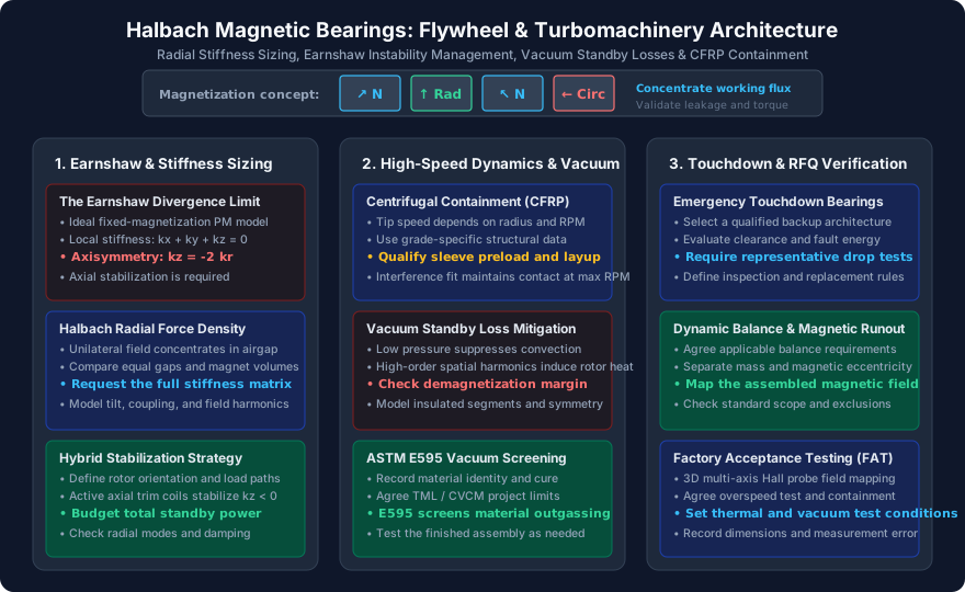
Halbach Magnetic Bearings for High-Speed Flywheels and Turbomachinery: Sizing Radial Stiffness, Overcoming Earnshaw Negative Stiffness, and Mitigating Vacuum Standby Losses
Size Halbach magnetic bearings for flywheels and turbomachinery. Compare stiffness, vacuum losses and touchdown risks; use the RFQ checklist for design reviews.
Halbach magnetic bearings can provide passive radial support, but they do not by themselves deliver stable suspension in every direction or zero-loss flywheel operation. For a flywheel, turbomolecular pump, or oil-free turbocompressor, the purchasing decision must cover magnetic stiffness, axial stabilization, rotor dynamics, heat rejection, containment, and emergency touchdown.
A Halbach arrangement rotates the magnetization direction between segments to concentrate flux toward a selected working region. Whether that improves bearing stiffness or reduces mass depends on the interacting rotor and stator geometry. There is no universal percentage advantage over conventional permanent-magnet rings, and back iron is not required by every conventional design.
This guide helps rotordynamics engineers and procurement teams screen a concept and prepare an RFQ. Its added value is a reproducible stiffness and standby-energy example, an architecture comparison, and a supplier acceptance checklist. The calculations are illustrative design screens, not measured product results or certified operating limits.
Need a review before freezing the rotor envelope? Send your rotor mass, speed range, airgap, and load cases so the magnetic assembly requirements can be discussed alongside the machine design.
Scope and review date: Published and reviewed November 1, 2026. Global, English-language guidance for preliminary selection of permanent-magnet and hybrid Halbach bearing assemblies. Final approval requires machine-specific electromagnetic, structural, thermal, and controls analysis plus testing. This article does not establish a safety rating, supplier certification, or compliance with a machinery standard.
The Electromagnetic Foundation: Earnshaw’s Theorem and the Stiffness Tensor
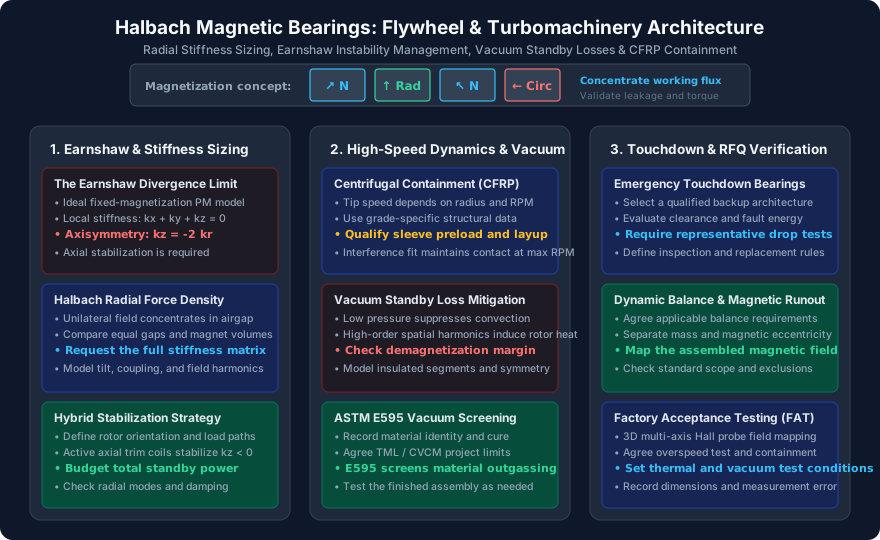
Figure 1: Conceptual engineering checklist. This summarizes design questions; it is not a field simulation or a record of a tested bearing.
The Earnshaw Divergence Constraint
For fixed-magnetization permanent magnets interacting across a source-free gap, static magnetic forces cannot create a stable restoring equilibrium in all translational directions. Under that idealization, define each local stiffness as the negative force derivative at the operating point:
ki = −∂Fi/∂xi
kx + ky + kz = 0
For an axisymmetric, uncoupled translational model:
kx = ky = kr  →  kz = −2kr
Here, kr is the stiffness along either transverse Cartesian axis, not the sum of both axes. The relation describes the ideal permanent-magnet subsystem; it does not specify the complete machine's stiffness after active forces, diamagnetism, induced currents, or constraints are added. Off-center operation, tilt, and cross-coupling require the full force and stiffness matrix.
Increasing radial stiffness without checking axial actuator authority can make the system harder to control. Ravaud, Lemarquand, and Lemarquand's force-and-stiffness study treats axially magnetized ring pairs; it is a modeling reference, not evidence of a fixed Halbach performance gain.
Unilateral Flux Concentration: What to Ask the Supplier to Model
A Halbach ring is a magnetization pattern, not a complete bearing architecture. Request the interacting rotor and stator arrangement, pole convention, segment count, end effects, working gap, and torque variation with angle. A rotating multipole field can create parasitic torque and losses when it passes conductive stationary parts.
Use Halbach ring assembly options to define the component envelope. Compare candidates using the same magnet volume, temperature, airgap, retention thickness, and load cases. Obtain force-displacement curves and a stiffness matrix rather than choosing by peak airgap flux density alone.
Architectural Comparison: PMB vs. AMB vs. Hybrid Halbach (HMB)
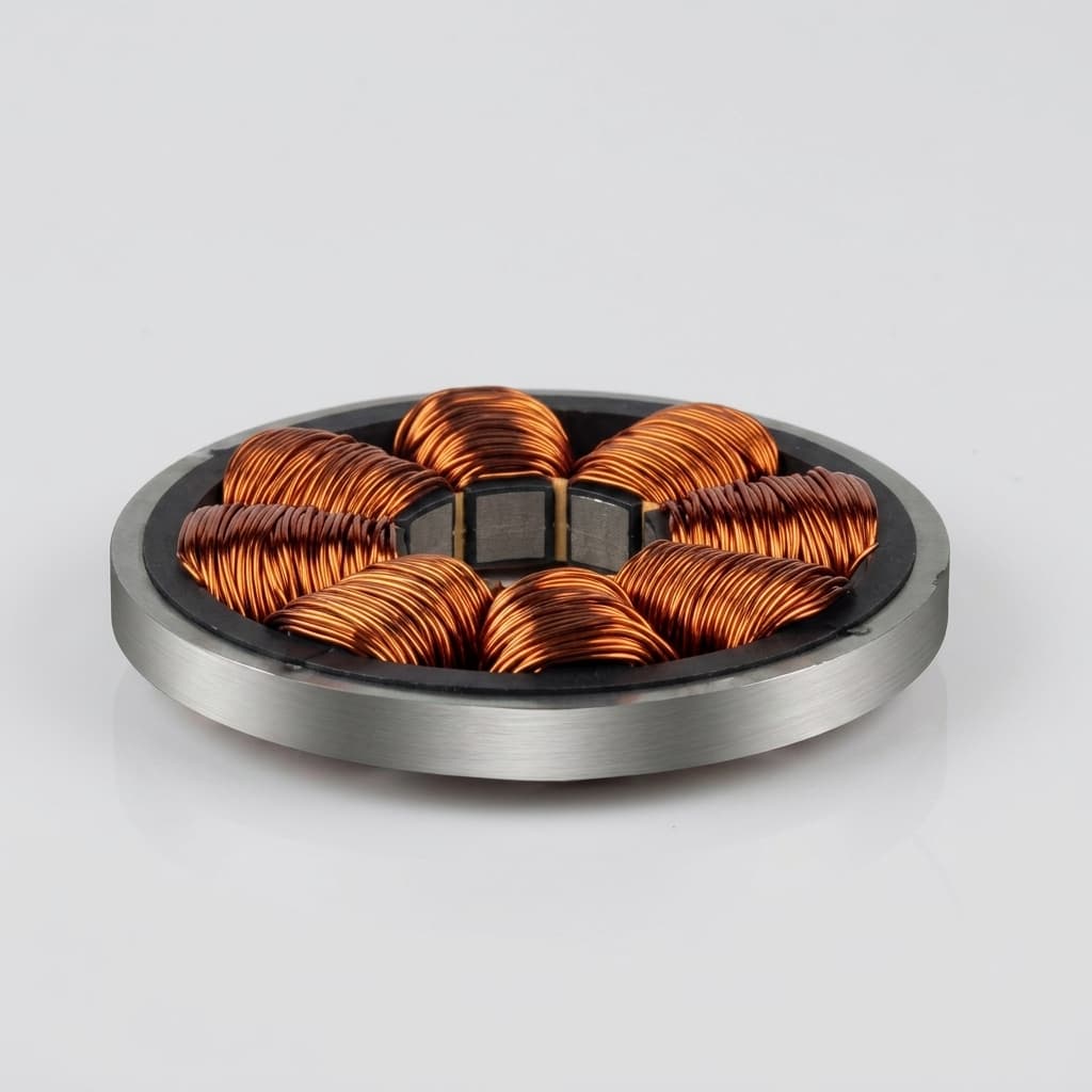
Figure 2: Catalogue illustration of a coil-based component. This image does not document a Halbach rotor, a containment sleeve, or validated high-speed performance.
Table 1: Magnetic Bearing Architecture Trade-off Matrix
| Engineering question | Fully active magnetic bearing (AMB) | Permanent magnets + electrodynamic stabilization | Hybrid passive-active bearing |
|---|---|---|---|
| Radial load support | Feedback-controlled electromagnetic force | Permanent-magnet forces in the selected supported axes | Passive magnets can carry a selected load component |
| Axial stability | Active control | Speed-dependent induced-current stabilizer must be designed | Active actuator or another explicit constraint |
| Suspension at zero speed | Possible with powered controls | Dynamic stabilizer is unavailable; mechanical support is needed | Depends on which axes remain actively controlled |
| Electrical standby draw | Include coils, amplifiers, sensors, and controller | No feedback amplifier is necessary for passive suspension; other machine loads remain | Include remaining control channels and bias current |
| Mechanical standby loss | Field harmonics and surrounding conductors still matter | Induced-current drag is part of the stabilization trade-off | Depends on field symmetry, segmentation, and conductive structures |
| Damping and critical speeds | Tunable within actuator and controller limits | Assess the speed-dependent stiffness and damping matrix | Passive radial support may still require added damping |
| Power-loss behavior | Requires a coast-down and backup-support strategy | Low-speed transition onto mechanical support must be managed | Loss of active axial support can still cause touchdown |
| Supplier acceptance evidence | Force/current maps, stability margins, and rotor response | Lift-off behavior, drag, and stability through the speed range | Combined magnetic, controls, thermal, and touchdown tests |
There is no architecture-wide standby wattage, cost, or efficiency guarantee. For magnetic-bearing and flywheel applications, compare complete loss budgets and demonstrated stability over startup, normal operation, shutdown, and faults.
The Hybrid Halbach Compromise
Passive radial rings with active axial stabilization are one candidate arrangement. Rotor orientation matters: a vertical rotor's weight is an axial load, while a horizontal rotor's weight creates radial bearing reactions. Bearing spacing, moments, tilt stability, and radial damping must also be included. A single axial actuator cannot be assumed to stabilize every rigid-body and flexible mode.
Sizing Radial Stiffness and Overcoming Earnshaw Instability
1. Start with Load and Allowed Displacement
As an initial linear screen, divide the transverse load by the displacement budget assigned to magnetic compliance. Keep separate allowances for mechanical runout, thermal growth, tolerances, and touchdown clearance.
Illustrative assumptions, not supplier specifications:
Transverse load for this screen: Fr = 120 N
Allowed compliance displacement: xr = 0.60 mm
Required combined radial stiffness: kr,total ≥ Fr/xr = 200 N/mm
This is a rigid-rotor translation estimate. Resolve individual bearing reactions from load position and bearing spacing, then calculate local tangent stiffness at the loaded position. The example does not prove that a real bearing pair retains axisymmetry or linear stiffness through that displacement.
2. Active Axial Trim Control Sizing
For a separate idealized, centered model, assume the combined radial stiffness along each transverse axis is 200 N/mm, the corresponding passive axial stiffness is −400 N/mm, and rotor mass is 20 kg:
m·z̈ − |kz|·z = Factuator
|kz| = 400 N/mm = 400,000 N/m
Unstable pole: ωp = √(|kz|/m) = 141.4 rad/s
Equivalent frequency: fp = ωp/(2π) = 22.5 Hz
At 0.20 mm axial offset: |kz|·|z| = 80 N
The actuator must counter that destabilizing force plus applicable gravity, process thrust, acceleration, and disturbance loads, with documented design margin. The 80 N example excludes those additional loads. For a vertical rotor, gravity alone adds approximately 196 N for the stated mass, with direction and equilibrium handled in the force balance.
The unstable pole identifies a control challenge; it is not a bandwidth specification. Sensor delay, amplifier dynamics, actuator saturation, flexible modes, and cross-coupling determine achievable stability. Do not approve a controller merely because its bandwidth exceeds a fixed multiple of fp.
3. Ambient Electrodynamic Stabilization
Post and Ryutov's ambient-temperature passive-bearing work describes combining permanent-magnet support with rotation-induced currents to stabilize an otherwise unstable displacement. Mechanical support is needed at rest and below the usable speed range.
For a simple loop, R/L is an electrical angular-frequency scale. Converting it to rotor speed requires the pole pattern and relative-motion frequency; it is not a universal lift-off RPM. Induced-current stabilization also creates drag. Require a speed-dependent stability and loss analysis rather than assuming positive damping in every rotor mode.
High-Speed Rotor Dynamics: Centrifugal Dilation & CFRP Containment
Magnet Brittleness vs. Centrifugal Hoop Stress
Sintered NdFeB and SmCo are brittle materials. Adhesive bonding alone does not establish rotor retention. A thin, continuous free-ring approximation provides a useful stress scale:
σθ ≈ ρ·ω²·rm² = ρ·v²
Assumed density ρ = 7,600 kg/m³
Assumed mean radius rm = 0.050 m; speed n = 45,000 rpm
ω = 2πn/60 = 4,712 rad/s
v = ωrm = 235.6 m/s
σθ ≈ 422 MPa
This arithmetic is not a stress solution for discrete magnets, adhesive joints, and a sleeve. It shows why structural retention analysis is necessary. Use grade-specific material data, contact mechanics, thermal expansion, sleeve preload, fatigue, manufacturing defects, and containment testing to establish allowable speed.
Pre-Stressed Carbon Fiber (CFRP) Sleeve Sizing
CFRP is a candidate retention material because of its strength-to-mass ratio. Carbon fibers are electrically conductive, and laminate conductivity and losses depend on fiber direction, layup, resin, and electrical connections. Neither zero eddy-current loss nor a universal reduction percentage is justified.
Metallic sleeves may also be viable if their mechanical, magnetic, and loss effects are acceptable. Compare candidates using actual field harmonics and operating temperatures. Specify contact-pressure margin from the structural model; no single interference pressure or overspeed multiplier qualifies every machine. Agree the overspeed test, dwell, containment, and acceptance criteria with the responsible machine designer.
Standby Losses in High Vacuum: Eddy Current Dissipation and Outgassing
Separate Electrical Draw from Rotor Heating
Reducing gas pressure suppresses windage and convective heat transfer. Rotor heat must still leave through radiation, any conductive paths, and residual gas transfer. Stator coil heat and rotor eddy-current heat have different thermal paths, so electrical draw cannot be treated as heat deposited entirely in the rotor.
Use a complete standby budget: controller and sensor power, active coils, motor-generator losses, bearing drag, windage, and any vacuum or cooling auxiliaries. Define which loads are inside the quoted system boundary.
Illustrative standby-energy comparison:
Usable energy at the start of standby = 20 kWh
Constant total standby load A = 300 W; load B = 25 W
Standby time = 10 h
Energy consumed: A = 3.00 kWh; B = 0.25 kWh
Fractions of initial usable energy: 15.0% and 1.25%
These assumed loads show how to compare quotations; they are not measured AMB or Halbach values. Standby depletion is separate from charge/discharge conversion losses and does not by itself establish round-trip efficiency.
Mechanisms of Rotational Eddy Losses in Halbach Bearings
Finite segmentation, end effects, and asymmetry can expose conductive structures to time-varying flux. At 40,000 rpm, mechanical frequency is 666.7 Hz; a field component with p cycles per revolution appears at p × 666.7 Hz to a stationary observer. A perfectly axisymmetric field is invariant under rotation and does not create that excitation simply because the rotor turns.
Model housing heating separately from currents induced in rotating magnets by stationary asymmetry. Candidate mitigations include reducing harmonics, electrically isolating magnet subsegments, interrupting conductive loops, and selecting nonconductive barriers where appropriate. Segmentation dimensions and insulation thickness must follow the loss, structural, and manufacturing analysis; no fixed block width guarantees an acceptable loss.
Require the supplier to state test speed, pressure, temperature, instrumentation, and loss-separation method. A coast-down test measures combined drag unless motor, windage, and other contributions are separated. Use a thermal model and temperature evidence to check demagnetization margin rather than assuming a particular wattage always causes thermal runaway.
Comparing supplier proposals? Request a review of stiffness curves and standby-loss assumptions, including the system boundary used for each power figure.
Vacuum Outgassing and Adhesive Selection
The NASA Outgassing Database provides material screening data using ASTM E595, including total mass loss (TML), collected volatile condensable material (CVCM), and water vapor regain (WVR). Match any record to the actual material and cure condition.
Specify project limits and the test method in the RFQ. E595 is a test method, not a universal industrial vacuum acceptance specification. WVR is a reported quantity, not an automatic 0.10% acceptance limit. A database entry or bake-out operation does not certify a finished assembly's pressure capability, contamination behavior, or leak rate.
Select adhesive, coating, and bake-out conditions together with the magnet grade and sleeve resin. There is no universal 120°C / 8-hour process. Require cure records and, where necessary, assembly pump-down, contamination, and leak-test evidence. Ni-Cu-Ni and Parylene coatings have different deposition processes; neither alone proves a vacuum-tight assembly.
Dynamic Balancing and Runout: Mechanical vs. Magnetic Eccentricity
Mechanical balancing corrects mass distribution. It does not directly correct variation in segment magnetization or the magnetic center. Request mechanical runout, residual unbalance, and magnetic field mapping as separate acceptance records.
Near an operating point, a local linear screen gives F ≈ kr × e for magnetic-center offset e. With an assumed kr = 200 N/mm and e = 0.020 mm, that force scale is 4 N. Actual excitation depends on field pattern, rotation, and cross-coupling; a magnetization tolerance alone cannot predict the center offset with a universal formula.
Set the balancing requirement from rotor behavior, speed, and the applicable standard and edition. If a rigid-rotor balance grade G is used, the specific unbalance relation is eper = G/ω with consistent units. A nominal G0.4 choice at 45,000 rpm corresponds to approximately 0.085 µm, or 0.085 g·mm/kg; that conversion does not justify choosing the grade or applying a rigid-rotor procedure to a flexible rotor. Provide dedicated correction features; alterations to magnets or a retention sleeve require structural review.
ISO 14839 Scope Is an Acceptance Boundary
The ISO 14839-2:2004 catalogue scope covers AMB-equipped industrial machines above 15 kW and excludes small-scale rotors such as turbomolecular pumps, spindles, and flywheels. Do not assume its vibration zones automatically apply to every machine discussed here. Establish applicability and the measurement procedure before citing compliance; there is no universal 20 µm limit for all Halbach bearings.
Auxiliary Touchdown Bearings and Drop Dynamics
Backup bearings must intercept the rotor before sensitive surfaces contact, including under thermal growth, tolerance extremes, rotor bending, and transient whirl. A nominal clearance equal to half the magnetic gap does not guarantee that result.
Ceramic-hybrid rolling bearings are one candidate, but their speed capability, lubrication, vacuum compatibility, heat capacity, and support damping require application-specific qualification. Other backup architectures may be appropriate. Neither a material name nor a generic drop-event count establishes survival.
If a supplier proposes magnetic cushioning, ask for force versus displacement, stored energy, drop simulations, and representative test records. Do not credit an impact or wear reduction without evidence under matching conditions. The acceptance plan should cover fault triggers, initial speed, rotor load, number of drops, coast-down, and inspection or replacement rules.
Material Selection and Sizing Matrix
Table 2: Magnet Grade and Containment Sleeve Selection Matrix
| Subsystem component | Candidate material | Selection driver | Evidence to request | Limitation to resolve |
|---|---|---|---|---|
| High-flux Halbach ring | Sintered NdFeB | Compact force and stiffness envelope | Grade-specific demagnetization curves at operating temperature | Load line, corrosion protection, and irreversible loss margin |
| Temperature-sensitive ring | SmCo 2:17 | Thermal stability and coercivity needs | Temperature-dependent magnetic and mechanical data | Brittleness, cost, geometry, and surface requirements |
| Supply-sensitive NdFeB segments | Grain-boundary-diffused grade | Coercivity and material availability | Lot certificate, process route, and actual composition | Size-dependent properties; composition alone does not prove regulatory compliance |
| Lightweight retention sleeve | CFRP laminate | Strength, preload, and rotating mass | Laminate allowables, cure record, and contact model | Conductivity, anisotropy, resin temperature, and vacuum behavior |
| Metallic retention sleeve | Titanium or another qualified alloy | Manufacture and mechanical integrity | Stress, fatigue, expansion, and eddy-loss analysis | Conductive-loop heating and airgap penalty |
| Stator barrier | Technical ceramic where suitable | Electrical isolation and vacuum boundary design | Material, joint, mechanical, and vacuum test records | Brittle fracture, joining, and other conductive components remain relevant |
| Backup bearing | Qualified rolling or other touchdown design | Fault energy and coast-down behavior | Representative drop and post-test inspection records | Speed, lubrication, wear, clearance, and service-life limits |
Use temperature-dependent assembly stiffness when comparing NdFeB and SmCo. Remanence drift is not identical to stiffness drift. For a simplified interaction where force scales with the product of two magnetizations, both members' temperature changes matter; use a validated model rather than transferring a remanence percentage directly to stiffness.
10-Point RFQ Specification Checklist for Sourcing Teams
Copy this checklist into the procurement package and replace the bracketed fields with machine-specific requirements. An incomplete requirement should remain an open item rather than becoming a supplier guarantee by default.
- Loads and stiffness: Rotor orientation, mass, bearing spacing, radial/axial/process loads, nominal gaps, force-displacement curves, stiffness matrix, and temperature range:
[inputs and acceptance limits]. - Magnetic topology: Rotor/stator arrangement, pole convention, segment count, magnetization directions, angular torque ripple, and stray-field restrictions:
[drawing and model revision]. - Magnet material: Grade, lot traceability, temperature-dependent demagnetization curves, coercivity margin, and coating:
[approved material specification]. - Containment: Operating and overspeed conditions, sleeve layup or alloy, interference/contact model, thermal expansion, and structural acceptance:
[responsible designer and evidence]. - Control and damping: Stabilization of every relevant mode, actuator force/current limits, sensor delay, stability margins, startup and shutdown behavior:
[analysis and test plan]. - Standby and thermal limits: Total electrical boundary, mechanical drag allocation, rotor/stator temperatures, vacuum pressure, and test duration:
[W, temperature limits, and method]. - Vacuum materials: Adhesive/resin/coating identity, cure and bake-out limits, agreed outgassing criteria, and assembly pump-down or leak requirements:
[test records]. - Balance and magnetic runout: Applicable balance standard/edition, rigid or flexible rotor procedure, mechanical runout, magnetic map, and correction features:
[acceptance values and uncertainty]. - Touchdown and faults: Backup clearance stack, fault cases, initial speeds, drop count, coast-down, inspection, and replacement criteria:
[qualified conditions]. - Factory acceptance and handover: Dimensional report, calibrated field map, spin and thermal records, applicable standards with scope justification, cleanliness/packaging, and deviations:
[signed acceptance package].
Frequently Asked Questions (FAQ)
Can a Halbach magnetic bearing provide completely passive stable levitation?
Static permanent-magnet support alone cannot provide stable restoring forces in every translational direction under the Earnshaw assumptions above. Rotation-induced stabilization can make a passive system possible over a designed speed range, but low-speed support, damping, and stability still need to be established for the complete rotor.
Why choose an 8-segment or 16-segment Halbach ring?
Segmentation can make the magnetization pattern manufacturable, but the appropriate count depends on field quality, assembly tolerance, losses, cost, and pole count. Compare field harmonics and stiffness under the same envelope. There is no general mass saving or flux improvement percentage associated with a segment count alone.
How much axial actuator force is needed for a hybrid bearing?
Start with the passive axial force-displacement curve, then add gravity, thrust, acceleration, and disturbance cases. Include stroke, saturation, and thermal margins. The worked example gives an 80 N destabilizing force at 0.20 mm for the assumed stiffness; it is not a complete actuator rating.
Does a passive Halbach bearing have zero standby loss?
Its static magnetic support needs no coil excitation. The complete machine can still consume control and auxiliary power and lose rotor energy through induced currents, windage, and motor-generator drag. Compare standby energy using the same duration, initial stored energy, and system boundary.
Why can a mechanically balanced rotor still vibrate on magnetic bearings?
Mass unbalance, magnetic eccentricity, insufficient damping, sensor errors, and flexible modes are separate effects. A mechanical balance certificate does not replace a magnetic map or a rotor response test. Use measured excitation and operating stiffness to investigate synchronous vibration.
When should SmCo 2:17 be selected instead of NdFeB?
Consider SmCo when its temperature behavior and demagnetization margin offer an advantage in the actual load line and thermal environment. Compare grade-specific curves, assembly stiffness, containment, cost, and availability. No single temperature cutoff applies to every NdFeB or SmCo grade and geometry.
Sources and Reference Boundaries
- R. Ravaud, G. Lemarquand, and V. Lemarquand (2009): Force and Stiffness of Passive Magnetic Bearings Using Permanent Magnets. Part 1: Axial Magnetization, IEEE Transactions on Magnetics, 45(7), 2996–3002. Supports analytical ring-bearing force/stiffness modeling, not the illustrative product values in this guide.
- R. F. Post and D. D. Ryutov (1998): Ambient-Temperature Passive Magnetic Bearings: Theory and Design Equations, LLNL report UCRL-JC-129214. Supports rotation-induced stabilization and the need for support below the usable speed range.
- International Organization for Standardization: ISO 14839-2:2004 — Evaluation of vibration. The catalogue defines machine scope and exclusions; use the applicable standard text and contract to establish acceptance requirements.
- NASA Goddard: Outgassing Database. Provides ASTM E595 material-screening information; it does not certify a completed bearing assembly.
The numerical examples are calculated from the assumptions printed beside them. No first-hand bearing test, customer result, commercial power rating, or independently verified supplier capability is claimed.
Engineer Your Halbach Magnetic Bearing Assembly
Prepare a drawing and duty profile before requesting a quotation: rotor orientation and mass, speed range, bearing spacing, operating gaps, radial and axial loads, vacuum pressure, temperature limits, standby-energy target, and required acceptance records.
Contact the engineering team to discuss the component scope and evidence needed for your project. Explore Halbach rings and magnetic-bearing applications to frame the assembly request. Confirm any proposed retention, vacuum qualification, and testing services explicitly in the quotation.
Author

Categories
More Posts
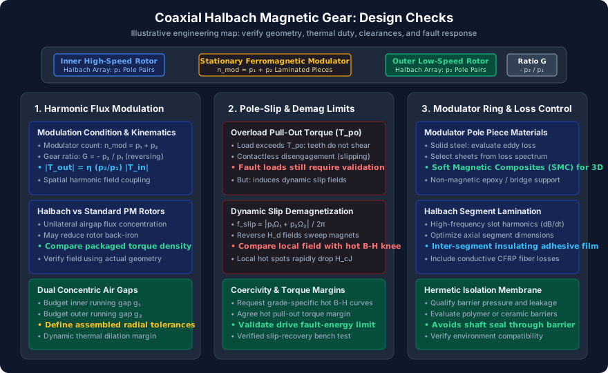
Coaxial Halbach Magnetic Gears: Sizing Modulated Flux Pole Pieces, Preventing Slip Demagnetization, and Mitigating Rotor Eddy Losses
Size coaxial Halbach magnetic gears: compare pole-piece geometry, slip protection, rotor eddy losses, and supplier evidence. Use the checklist for your next RFQ.

Halbach Array Manufacturing: Cost vs. Yield in Assembly-First vs. Magnetize-Later Techniques
Compare Halbach array assembly-first vs magnetize-later manufacturing by cost, yield, grade limits, supplier checks, and RFQ timing.

Segmented Halbach Arrays vs. Solid Rings: Managing Eddy Current Losses and Sourcing Costs
Compare segmented Halbach arrays and solid rings for eddy current loss control, sourcing cost trade-offs, and RFQ checks for high-speed magnet rotors.