Estimate lifting force requirements using the load calculator, then review system architectures, control limitations, and hybrid permanent magnet integration.
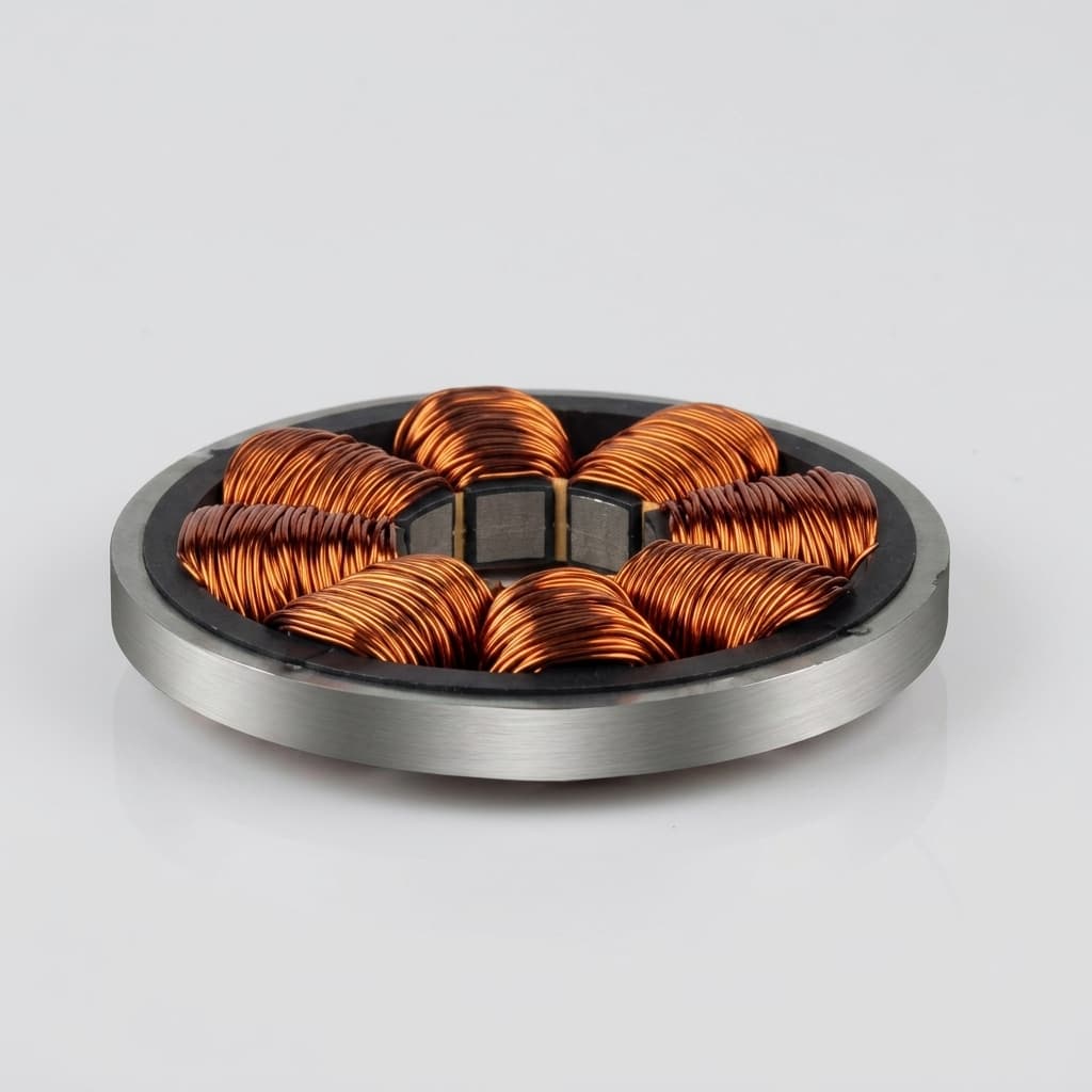
AMBs eliminate mechanical wear, lubrication requirements, and particle generation. Commercial examples show magnetic bearing machines at 500,000 rpm and above; practical speed limits still depend on rotor diameter, sleeve stress, eddy-current losses, and control bandwidth.
Evidence: Celeroton technology page, checked 2026-06-26.
Unlike passive bearings or mechanical ball bearings, the stiffness and damping of an AMB are electronically programmable. The controller actively suppresses vibrations across critical speeds, increasing rotor stability.
Evidence: AMB design literature and ISO 14839-1:2018 terminology.
The bearing itself is inherently unstable (Earnshaw's Theorem). It relies entirely on closed-loop feedback at high bandwidth. Fail-safe backup bearings (typically set at ~0.5x the AMB air gap) are mandatory to prevent catastrophic crashes during power loss.
Boundary: controller bandwidth is design-specific and stability margins must be verified via ISO 14839-3 (SNTF) or API 617 Annex E when the compressor specification requires it.
A complete active magnetic bearing system is not just a magnet; it is a high-speed mechatronic loop consisting of four major subsystems.
Typically formed by laminated silicon steel stators wound with copper coils. The electromagnets generate the attractive force that pulls the rotor into the center. Because magnetic force is attractive and nonlinear (proportional to 1/gap²), opposing pairs of electromagnets operate in a differential driving mode to linearize control.
Eddy-current or inductive displacement sensors monitor the rotor's exact position in microns. A DSP or FPGA-based controller processes this feedback, executing PID or advanced robust control algorithms (e.g., H-infinity) thousands of times per second to command the power amplifiers.
Use flux density and pole area to estimate the theoretical attractive force. Treat this as a feasibility screen, not a purchase specification.
Match current, amplifier slew rate, sensor resolution, and controller bandwidth to the rotor modes that need damping.
Validate touchdown bearings, containment, magnet retention, thermal margins, and maintenance access before release.
Fig 1. Standard AMB Control Loop: A continuous feedback cycle requiring high-bandwidth amplifiers, sub-millisecond control logic, and high-resolution displacement sensors.
To offset the static weight of heavy rotors, engineers design Hybrid Magnetic Bearings. Permanent magnets such as NdFeB or SmCo Halbach arrays can provide part of the bias flux so the electromagnets focus on dynamic correction. The expected power and cooling reduction is design-specific; public evidence is strongest for the general bias-flux principle, while exact savings require a coil-current and duty-cycle model. However, this introduces thermal boundaries: rotor/stator temperatures must not exceed the magnet's continuous operating limit, and high-speed rotors may need carbon-fiber or titanium sleeves to retain the magnet segments.
The page uses public references for concepts and benchmarks, then separates what is suitable for first-pass sizing from what still needs project-specific analysis.
| Decision Claim | Evidence | Confidence | Limit |
|---|---|---|---|
| AMB force sizing starts with air-gap flux density and pole area. | Schweitzer & Maslen; calculator formula | High for first-pass sizing | Uniform flux, negligible fringing, and no saturation are assumed. Max specific load is generally ~30-40 N/cm² due to ~1.5T iron saturation limit. |
| Closed-loop control and backup bearings are mandatory design topics. | ISO 14839-1:2018 vocabulary; ISO 14839-3:2006 stability margin; AMB design literature | High | Touchdown (backup) bearing radial clearance must typically be ~0.5 of the AMB air gap. The page does not certify a machine against ISO 14839-3 or API 617 Annex E stability criteria. |
| High-speed AMBs can exceed conventional bearing speed envelopes. | Celeroton commercial technology page | Medium | Vendor speed claims are application-specific; DN limits must be recalculated from rotor diameter and speed. |
| Flywheel AMB projects need rotordynamics, FEA, and touchdown review. | NASA NTRS G2 flywheel module design | Medium | NASA record describes a lab-oriented aerospace flywheel module; production containment and certification evidence remains project-specific. |
Use the calculator to screen pole force, then use the application context to decide whether active control, permanent magnet bias, or a simpler bearing technology deserves the next design pass.
| Application | Why AMB Helps | Halbach Role | Must Check Next |
|---|---|---|---|
| Oil-free turbocompressor or turboexpander | Eliminates process oil, supports high speed, and enables sealed motor-compressor packaging. | Bias-flux assist can reduce steady-state coil current when temperature and retention margins are proven. | ISO 14839-3 SNTF margin, API 617 Annex E when specified, touchdown energy, and separation margins. |
| Flywheel or vacuum energy storage rotor | Avoids bearing drag and lubrication inside vacuum while supporting high rotor surface speed. | Permanent magnet bias can lower standby loss, but containment and demagnetization risk dominate sourcing. | Rotor burst containment, eddy-current loss, touchdown spin-down, FEA force map, and thermal soak. |
| Precision spindle, test rig, or cleanroom tool | Programmable stiffness and no contact wear can reduce particles and improve repeatable runout control. | Useful when static load is predictable; less useful when disturbance force changes quickly. | Sensor noise, amplifier bandwidth, thermal drift, backup bearing clearance, and service access. |
| Heavy industrial rotor with low speed | AMB may add diagnostics and oil-free operation, but magnetic specific load is not automatically higher than contact bearings. | Hybrid bias can help carry weight, yet large pole area may reduce rotor dynamic margin. | Pole area envelope, stator saturation, installation stiffness, downtime cost, and fallback bearing load. |
| Bearing Type | Load Capacity | Speed Limit | Complexity & Cost |
|---|---|---|---|
| Active Magnetic (AMB) | Moderate (~30-40 N/cm²). Limited by iron saturation (~1.5T). | Very high when rotor stress, eddy-current loss, and control bandwidth are solved; vendor examples reach 500,000 rpm+. | Very High. Requires DSP, amps, sensors, and backup bearings. |
| Passive Magnetic (PMB) | Low to Moderate. Uses repulsion. | High, but susceptible to dynamic instabilities. | Low. Cannot stabilize all degrees of freedom alone. |
| Ceramic Ball Bearing | Very High (~205 N/cm²). Direct contact transfer. | Moderate (< 2M DN). Limited by friction, heat, and lubrication breakdown. | Low to Moderate. Consumable part needing replacement. |
Screening context: AMB specific load is constrained by iron saturation and pole area; vendor speed examples are application specific and were checked against the cited Celeroton page on 2026-06-26. Recalculate DN, sleeve stress, thermal loss, and stability margins for the actual rotor before selecting a bearing family.
| Misuse Risk | Decision Impact | Mitigation |
|---|---|---|
| Using calculator force as final load rating | Oversized force number with hidden coil heating or saturation | Run 2D/3D magnetic FEA, current density checks, and thermal rise estimates before RFQ freeze. Respect the ~40 N/cm² hard limit. |
| Ignoring power-loss touchdown | Rotor crash during controller fault or site power interruption | Specify catcher bearing clearance (usually ~0.5x AMB air gap), impact energy, spin-down time, and allowed rub events. |
| Ignoring control loop stability margins | System goes unstable under process load or rotor thermal expansion | Evaluate Sensitivity Transfer Function (SNTF) per ISO 14839-3; for compressor projects, compare contract requirements against API 617 Annex E rather than assuming equivalence. |
| Treating Halbach magnets as a full AMB substitute | Unstable degrees of freedom or uncontrolled rotor modes | Use Halbach arrays as bias-flux or passive assist elements while retaining active control where stability is required. |
| Selecting NdFeB without thermal margin | Irreversible demagnetization and loss of bias flux | Compare rotor/stator temperatures against magnet grade limits and consider SmCo for hot or vacuum environments. |
A force estimate becomes actionable only when it is paired with the geometry, thermal, and failure-mode information needed to quote or review a hybrid magnetic bearing component.
| RFQ Input | Why It Matters | Minimum Detail |
|---|---|---|
| Calculated force target | Connects the estimator output to the load case for each pole or axis. | Normal load, disturbance load, safety factor, load direction, and whether the force is per pole or per bearing axis. |
| Rotor and stator envelope | Turns theoretical pole area into manufacturable magnet and lamination geometry. | Rotor OD/ID, axial length, pole count, available radial stack, target air gap, and tolerance band. |
| Speed and duty cycle | Defines retention sleeve stress, eddy-current loss, and control bandwidth requirements. | Rated speed, overspeed, acceleration profile, dwell time, vacuum or gas environment, and expected starts per day. |
| Thermal boundary | Prevents irreversible demagnetization and coil thermal runaway. | Rotor/stator temperature, cooling path, bakeout or sterilization exposure, and preferred NdFeB or SmCo grade. |
| Failure mode and touchdown case | AMB sourcing is incomplete without a power-loss mechanical support plan. | Touchdown bearing clearance, maximum rub events, spin-down time, containment target, and inspection interval. |
| Verification package | Separates component quotation from release-ready AMB system approval. | 2D/3D magnetic FEA, rotordynamic model, SNTF or contract standard target, coating spec, and balance grade. |
Practical next step: send the estimator output with rotor envelope, speed, temperature, and touchdown assumptions. Halbach Magnet can then separate magnet-array manufacturability from the larger AMB controller and safety-case work owned by the system integrator.
Send Hybrid AMB InputsAn AMB is a system that suspends a rotating shaft in a magnetic field without physical contact. It relies on a high-speed control loop monitoring the rotor position and adjusting electromagnet currents continuously to maintain levitation.
No. It estimates first-pass magnetic force from flux density and pole area only. A release-ready AMB design still needs coil current, thermal rise, rotor dynamics, touchdown bearing, and FEA checks.
The calculator uses the ideal Maxwell stress relation after a target air-gap flux density is already assumed. In real hardware, a larger air gap usually requires more ampere-turns, creates more leakage, increases coil heating, and makes control harder.
AMB load capacity is limited by magnetic saturation in the iron path, often around 1.5 to 1.6 T. That creates a practical specific-load limit near 30-40 N/cm2 of pole face area, so heavy rotors can require large bearings that must be checked against rotor dynamics.
Levitation is immediately lost. Commercial AMB systems incorporate mechanical touchdown or catcher bearings that support the rotor until it spins down, with clearance and rub energy sized for the fault case.
ISO 14839-3 is the core public reference for AMB stability-margin evaluation. API 617 Annex E can also apply to magnetic-bearing compressors when the project specification requires it.
No. Permanent magnets can provide bias flux or passive assist, but they do not stabilize all degrees of freedom in a rotating machine. Active control is still required wherever dynamic stability is required.
A conventional rolling or fluid-film bearing can be the better choice when load density, low first cost, simple maintenance, or mature certification is more important than oil-free operation, low particle generation, or programmable dynamics.
A Halbach array concentrates flux toward the working air gap and can provide static bias force without continuous coil power. The benefit depends on the magnetic circuit, thermal envelope, rotor retention system, and control authority.
Provide rotor diameter, speed range, air gap, target bias flux, operating temperature, containment preference, coating requirements, and whether the magnet will sit in a radial, axial, or conical bearing circuit.
NdFeB usually provides higher flux density, while SmCo gives better high-temperature margin and corrosion resistance. The right choice depends on continuous temperature, transient heat, vacuum exposure, and allowable package size.
The minimum RFQ package should include force target, envelope, speed, temperature, coating, magnet grade preference, containment concept, and whether Halbach Magnet should review magnetic FEA or provide only manufactured components.
We manufacture tight-tolerance Halbach arrays and high-speed carbon fiber sleeved rotors tailored for hybrid magnetic bearing applications.
Inquiry Email
